802.11be Downlink Multi-User MIMO and OFDMA Throughput Simulation
This example shows transmit and receive processing for an IEEE® 802.11be™ (Wi-Fi 7) extremely high throughput (EHT) multi-user (MU) downlink transmission over a TGax indoor fading channel. It simulates two PPDU types: MU-MIMO and OFDMA.
Introduction
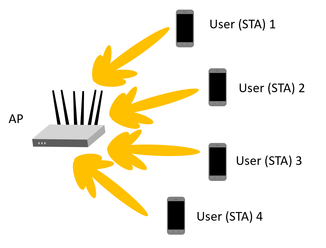
This example simulates an access point (AP) transmitting to four stations (STAs) simultaneously using the EHT MU packet format as specified in [1].
You can configure the EHT MU format for MU-MIMO transmission or OFDMA transmission. This flexibility allows an EHT MU packet to transmit to a single user over the whole band, or multiple users over different parts of the band (OFDMA). In this example, two transmission PPDU types are simulated for the multi-user downlink scenario:
MU-MIMO transmission - all four users share the full band.
OFDMA transmission - two users share a large-size multiple resource unit (MRU), and the remaining two users are assigned a single resource unit (RU) each.
For a detailed overview of 802.11be PPDU types, see the 802.11be Waveform Generation example.
For each PPDU type, the AP transmits a burst of 10 packets, and each STA demodulates and decodes the data intended for it. An evolving TGax indoor MIMO channel with AWGN is modeled between the AP and each STA. The raw AP throughput is calculated by counting the number of packets transmitted successfully to all STAs. The simulation repeats for different path losses. In this example, all the transmissions are beamformed. Therefore, before simulating the data transmission, the channel between the AP and each station is sounded under perfect conditions to obtain the channel state information (CSI).
Transmission Configuration
Use a wlanEHTMUConfig object to configure the transmission of an EHT MU packet. Specify two transmission configuration objects to define the two different AP transmissions:
cfgMUMIMOis an 80 MHz MU-MIMO configuration that consists of a single 996-tone RU with four users. Each user has one space-time stream.cfgOFDMAis an 80 MHz OFDMA configuration that consists of a 484+282-tone MRU with two users, a 106-tone and a 106+26-tone RU, each with one user. Each user has two space-time streams.
The other transmission parameters, such as the guard interval, EHT-LTF type, APEPLength, and MCS, are the same for all users in all configurations.
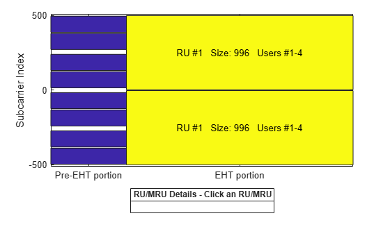
First, define an 80 MHz bandwidth and a single 996-tone RU with four users for the MU-MIMO configuration. For a description of multiple users in an MU-MIMO configuration over the full channel bandwidth, see the 802.11be Waveform Generation example.
% MU-MIMO configuration - 4 users on one 996-tone RU
cfgMUMIMO = wlanEHTMUConfig('CBW80','NumUsers',4);
The allocation plot shows a single RU assigned to all four users.
showAllocation(cfgMUMIMO);
Configure the transmission parameters for each user.
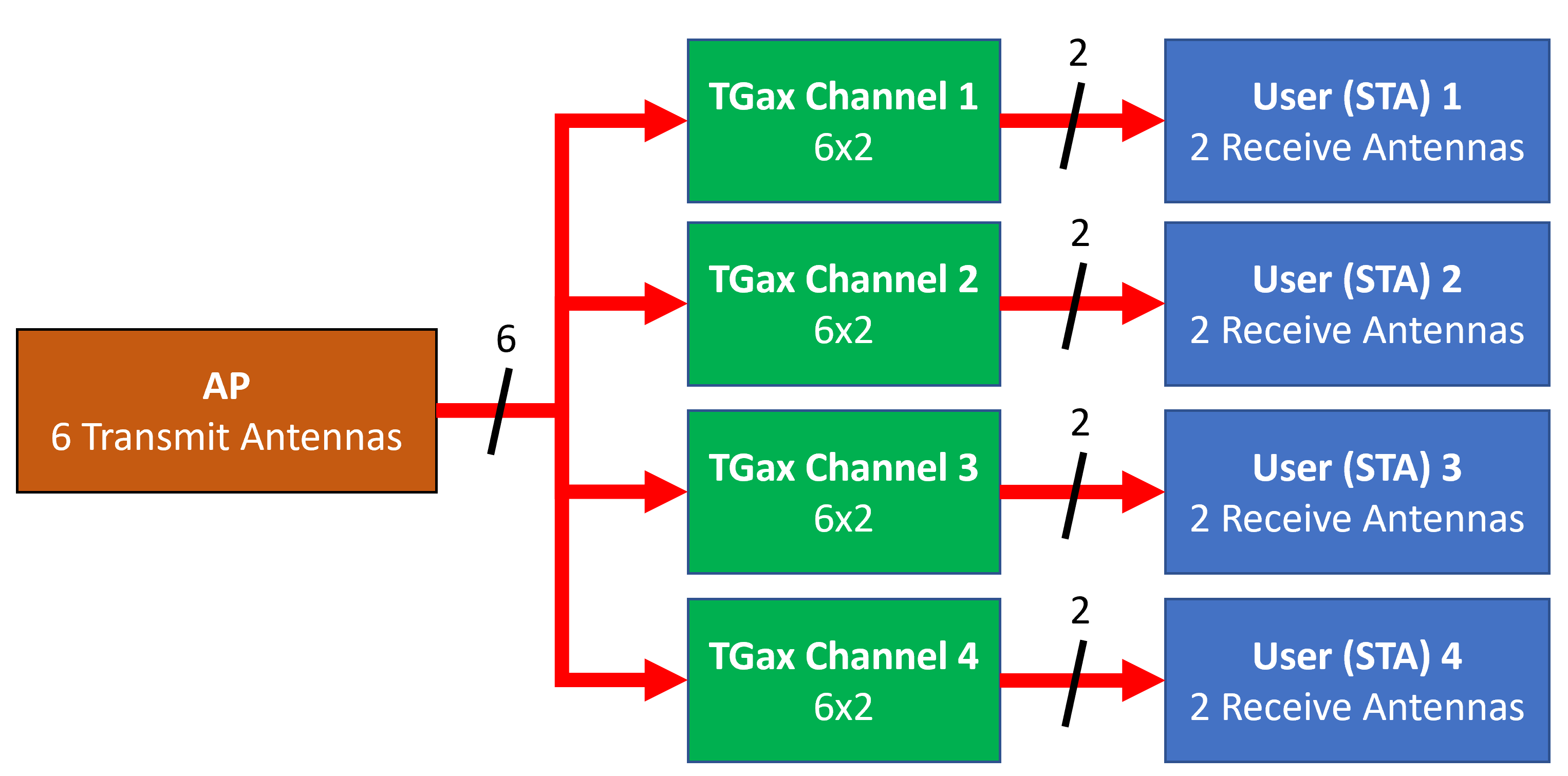
numTx = 6; % Number of transmit antennas
guardInterval = 3.2; % Guard interval in microseconds
ltfType = 4; % EHT-LTF type
apepLength = 1e3; % APEP length in bytes
mcs = 4; % MCS

% Configure common parameters for all users
cfgMUMIMO.NumTransmitAntennas = numTx;
cfgMUMIMO.GuardInterval = guardInterval;
cfgMUMIMO.EHTLTFType = ltfType;

% Configure per user parameters
% STA #1
cfgMUMIMO.User{1}.NumSpaceTimeStreams = 1;
cfgMUMIMO.User{1}.MCS = mcs;
cfgMUMIMO.User{1}.APEPLength = apepLength;
% STA #2
cfgMUMIMO.User{2}.NumSpaceTimeStreams = 1;
cfgMUMIMO.User{2}.MCS = mcs;
cfgMUMIMO.User{2}.APEPLength = apepLength;
% STA #3
cfgMUMIMO.User{3}.NumSpaceTimeStreams = 1;
cfgMUMIMO.User{3}.MCS = mcs;
cfgMUMIMO.User{3}.APEPLength = apepLength;
% STA #4
cfgMUMIMO.User{4}.NumSpaceTimeStreams = 1;
cfgMUMIMO.User{4}.MCS = mcs;
cfgMUMIMO.User{4}.APEPLength = apepLength;
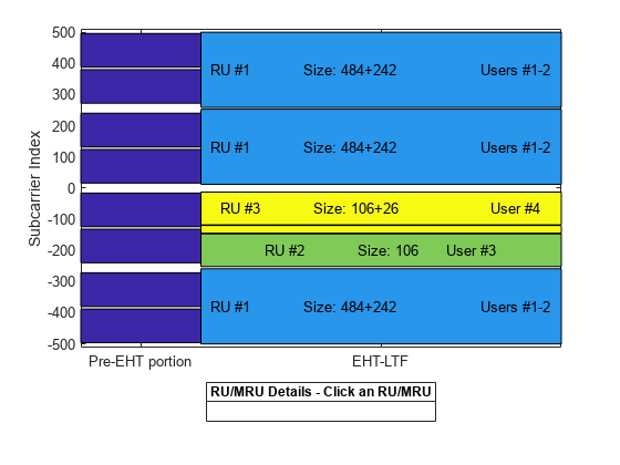
Next, define the OFDMA configuration. The allocation index [105 50 29 29] defines a 484+242-tone MRU with two users as well as a 106+26-tone and 106-tone RU, each serving a single user.
% OFDMA configuration - 4 users, two on a 484+242-tone MRU, one on a
% 106+26-tone RU, and one on 106-tone RU
cfgOFDMA = wlanEHTMUConfig([105 50 29 29]);
The allocation plot shows the MRU with two users and two RUs, each with a single user. When comparing this allocation plot to the full band MU-MIMO plot, you can see that the total number of subcarriers used (484+242+106+26+106 = 964 subcarriers) is less than the MU-MIMO allocation (996 subcarriers). The smaller number of subcarriers allows guards between MRU and single RU users.
showAllocation(cfgOFDMA);
Configure the transmission parameters for each user.
% Configure common parameters for all users
cfgOFDMA.NumTransmitAntennas = numTx;
cfgOFDMA.GuardInterval = guardInterval;
cfgOFDMA.EHTLTFType = ltfType;

% Configure per user parameters
% STA #1 (RU #1)
cfgOFDMA.User{1}.NumSpaceTimeStreams = 2;
cfgOFDMA.User{1}.MCS = mcs;
cfgOFDMA.User{1}.APEPLength = apepLength;
% STA #2 (RU #1)
cfgOFDMA.User{2}.NumSpaceTimeStreams = 2;
cfgOFDMA.User{2}.MCS = mcs;
cfgOFDMA.User{2}.APEPLength = apepLength;
% STA #3 (RU #2)
cfgOFDMA.User{3}.NumSpaceTimeStreams = 2;
cfgOFDMA.User{3}.MCS = mcs;
cfgOFDMA.User{3}.APEPLength = apepLength;
% STA #4 (RU #3)
cfgOFDMA.User{4}.NumSpaceTimeStreams = 2;
cfgOFDMA.User{4}.MCS = mcs;
cfgOFDMA.User{4}.APEPLength = apepLength;
Channel Model Configuration
A TGax indoor channel model is used in this example. An individual channel is used to simulate the link between the AP and each user. Create a TGax channel object, tgaxBase, with properties relevant for all users. In this example, the delay profile (Model-B) and the number of receive antennas are common for all users. When the distance between transmitter and receiver is greater than or equal to 5 meters, Model-B is considered non-line of sight. This is described further in wlanTGaxChannel. Use a fixed seed for the channel per user to allow repeatability.
% Create channel configuration common for all users
tgaxBase = wlanTGaxChannel;
tgaxBase.DelayProfile = 'Model-B';     % Delay profile
tgaxBase.NumTransmitAntennas = numTx;  % Number of transmit antennas
tgaxBase.NumReceiveAntennas = 2;       % Each user has two receive antennas
tgaxBase.TransmitReceiveDistance = 5;  % Non-line of sight distance
tgaxBase.ChannelBandwidth = cfgMUMIMO.ChannelBandwidth;
tgaxBase.SampleRate = wlanSampleRate(cfgMUMIMO);
tgaxBase.RandomStream = 'mt19937ar with seed';
Next, create a channel for each user. The channel for each user is a clone of tgaxBase, with a unique UserIndex property, stored in a cell array tgax. Set the UserIndex property of each individual channel to provide a unique channel for each user. The resultant channels are shown below.
% A cell array stores the channel objects, one per user
numUsers = numel(cfgMUMIMO.User); % Number of users simulated in this example
tgax = cell(1,numUsers);

% Generate per-user channels
for userIdx = 1:numUsers
    tgax{userIdx} = clone(tgaxBase);
    tgax{userIdx}.Seed = userIdx; % Set unique initial seed per channel user
    tgax{userIdx}.UserIndex = userIdx; % Set unique user index
end
Simulation Settings
This example simulates different path losses. To set up for path loss simulation, apply the same path loss and noise floor to all users. For each path loss specify 10 packets to pass through the channel. Separate the packets by 20 microseconds. Specify single precision receiver processing to accelerate the simulation.
cfgSim = struct;
cfgSim.NumPackets = 10;       % Number of packets to simulate for each path loss
cfgSim.Pathloss = (97:2:103); % Path loss to simulate in dB
cfgSim.TransmitPower = 30;    % AP transmit power in dBm
cfgSim.NoiseFloor = -89.9;    % STA noise floor in dBm
cfgSim.IdleTime = 20;         % Idle time between packets in μs
cfgSim.DataType = 'single';   % Data type ('single' or 'double') of received packets
Beamforming Feedback
Transmit beamforming for both MU-MIMO and OFDMA relies on knowledge of the channel state between transmitter and receiver at the beamformer. To set up the channel for beamforming in this example, each STA provides feedback of the per-subcarrier channel state using channel sounding. The AP transmits a null data packet (NDP), and each STA uses this packet to determine the channel state. They then feed the channel state back to the AP. The same process is used for the 802.11ax Downlink OFDMA and Multi-User MIMO Throughput Simulation example. The ehtUserBeamformingFeedback helper function detects the NDP and uses channel estimation to determine the CSI. Singular value decomposition (SVD) is then used to calculate the beamforming feedback.
% Create an NDP with the correct number of space-time streams to generate
% enough LTF symbols
cfgNDP = wlanEHTMUConfig(tgaxBase.ChannelBandwidth);
cfgNDP.GuardInterval = guardInterval;
cfgNDP.EHTLTFType = ltfType;
cfgNDP.NumTransmitAntennas = cfgMUMIMO.NumTransmitAntennas;
cfgNDP.User{1}.APEPLength = 0; % No data in an NDP
cfgNDP.User{1}.NumSpaceTimeStreams = cfgMUMIMO.NumTransmitAntennas;

% Generate NDP packet - with an empty PSDU as no data
txNDP = cast(wlanWaveformGenerator([],cfgNDP), cfgSim.DataType);

% For each user STA, pass the NDP packet through the channel and calculate
% the feedback channel state matrix by SVD.
staFeedback = cell(1,numUsers);
for userIdx = 1:numel(tgax)
    % Received waveform at user STA with 50 sample padding. No noise.
    rx = tgax{userIdx}([txNDP; zeros(50,size(txNDP,2),'like',txNDP)]);

    % Get the full-band beamforming feedback for a user
    staFeedback{userIdx} = ehtUserBeamformingFeedback(rx,cfgNDP);
end
MU-MIMO Simulation
For this exercise, you first simulate the MU-MIMO configuration. To calculate the beamforming matrix for an RU given the CSI feedback for all users in the MU-MIMO allocation, use the ehtMUCalculateSteeringMatrix helper function. Use a zero forcing solution to calculate the steering matrix within the helper function.
% Calculate the steering matrix to apply to the RU given the feedback
ruIdx = 1; % Index of the one and only RU
steeringMatrix = ehtMUCalculateSteeringMatrix(staFeedback,cfgMUMIMO,cfgNDP,ruIdx);

% Apply the steering matrix to the RU
cfgMUMIMO.RU{1}.SpatialMapping = 'Custom';
cfgMUMIMO.RU{1}.SpatialMappingMatrix = steeringMatrix;
The ehtMUSimulateScenario helper function performs the simulation. The pre-EHT preamble of 802.11be is backwards compatible with 802.11ac. Therefore, in this example, the front-end synchronization components for a VHT waveform are used to synchronize the EHT waveform at each STA. For each packet and path loss simulated, the following process occurs:
A PSDU is created and encoded to create a single packet waveform.
The waveform is passed through an evolving TGax channel model and AWGN is added to the received waveform. The channel state is maintained between packets.
The packet is detected.
Coarse carrier frequency offset is estimated and corrected.
Fine timing synchronization is established.
Fine carrier frequency offset is estimated and corrected.
The EHT-LTF is extracted from the synchronized received waveform. The EHT-LTF is OFDM demodulated and channel estimation is performed.
The EHT-Data field is extracted from the synchronized received waveform and OFDM demodulated.
Common pilot phase tracking is performed to track any residual carrier frequency offset.
The phase corrected OFDM symbols are equalized with the channel estimate.
Noise estimation is performed using the demodulated data field pilots and single-stream channel estimate at pilot subcarriers.
The equalized symbols are demodulated and decoded to recover the PSDU.
The recovered PSDU is compared to the transmitted PSDU to determine if the packet has been recovered successfully.
Run the simulation for the MU-MIMO configuration.
disp('Simulating MU-MIMO...');Simulating MU-MIMO...
throughputMUMIMO = ehtMUSimulateScenario(cfgMUMIMO,tgax,cfgSim);
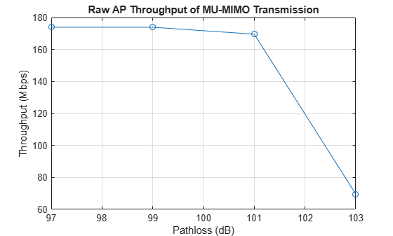
 Pathloss 97.0 dB, AP throughput 173.9 Mbps
 Pathloss 99.0 dB, AP throughput 173.9 Mbps
 Pathloss 101.0 dB, AP throughput 169.6 Mbps
 Pathloss 103.0 dB, AP throughput 69.6 Mbps
Plot the raw AP throughput of the MU-MIMO simulation. The throughput accounts for the packet duration including the idle time, the APEP length of each user, and the number of successfully decoded packets. The results show for this channel realization at high SNRs (low path loss) that the throughput provided by the MU-MIMO configuration is considerable. However, the throughput drops dramatically when the noise dominates (low SNRs).
% Sum throughput for all STAs and plot for all configurations
figure;
plot(cfgSim.Pathloss,sum(throughputMUMIMO,2),'-o');
grid on;
xlabel('Pathloss (dB)');
ylabel('Throughput (Mbps)');
title('Raw AP Throughput of MU-MIMO Transmission');
OFDMA Simulation
Now simulate the OFDMA configuration and transmit beamforming.
Calculate the steering matrix for each RU by using the feedback from the STAs. To calculate the beamforming matrix for an RU given the CSI feedback, use the ehtMUCalculateSteeringMatrix helper function..
% For each RU, calculate the steering matrix to apply
for ruIdx = 1:numel(cfgOFDMA.RU)
    % Calculate the steering matrix to apply to the RU given the feedback
    steeringMatrix = ehtMUCalculateSteeringMatrix(staFeedback,cfgOFDMA,cfgNDP,ruIdx);

    % Apply the steering matrix to each RU
    cfgOFDMA.RU{ruIdx}.SpatialMapping = 'Custom';
    cfgOFDMA.RU{ruIdx}.SpatialMappingMatrix = steeringMatrix;
end
Run the simulation for the OFDMA configuration.
disp('Simulating OFDMA...');Simulating OFDMA...
throughputOFDMA = ehtMUSimulateScenario(cfgOFDMA,tgax,cfgSim);
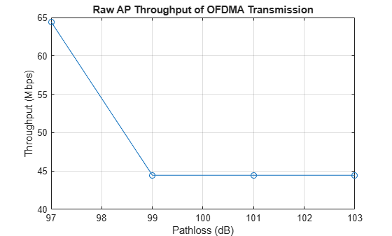
 Pathloss 97.0 dB, AP throughput 64.4 Mbps
 Pathloss 99.0 dB, AP throughput 44.4 Mbps
 Pathloss 101.0 dB, AP throughput 44.4 Mbps
 Pathloss 103.0 dB, AP throughput 44.4 Mbps
Plot the raw AP throughput of the OFDMA simulation. The results show that, as the path loss increases, several packets fail to be decoded for some users and the overall raw throughput drops.
% Sum throughput for all STAs and plot for all configurations
figure;
plot(cfgSim.Pathloss,sum(throughputOFDMA,2),'-o');
grid on;
xlabel('Pathloss (dB)');
ylabel('Throughput (Mbps)');
title('Raw AP Throughput of OFDMA Transmission');
Conclusion
This example shows how to simulate the downlink throughput for MU-MIMO and OFDMA configurations of 802.11be waveforms. Because throughput depends on many factors that differ between the two cases, such as RU size and the number of space-time streams, comparing the downlink throughput of MU-MIMO and OFDMA configurations is challenging.
In this example, for the OFDMA configuration, the RU sizes of User 3 and User 4 are much smaller than those of User 1 and User 2. The APEP length is the same for all users. Therefore, the OFDMA packet duration is limited by the smallest RU size, resulting in a long packet duration and a limited throughput.
References
IEEE Std 802.11be™/D7.0 Draft Standard for Information technology - Telecommunications and information exchange between systems Local and metropolitan area networks - Specific requirements - Part 11: Wireless LAN Medium Access Control (MAC) and Physical Layer (PHY) Specifications. Amendment 8: Enhancements for Extremely High Throughput (EHT).