Tuning Cascade Control and Current Control PID Loops in a PMLSM model
Hi Everyone,
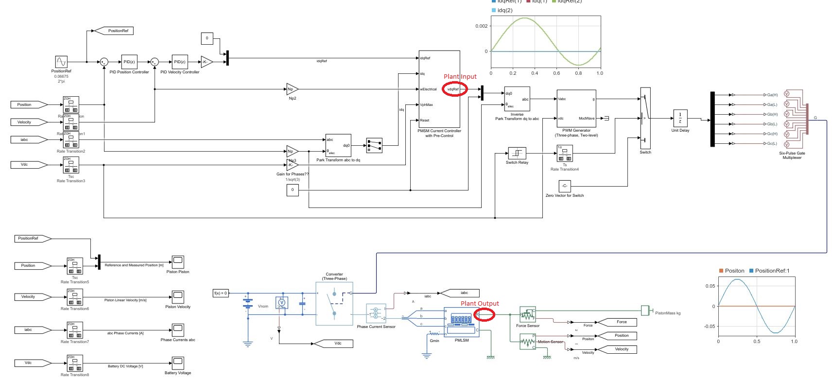
Require some guidance and pointers on model ee_pmlsm_drive please.

Its regarding a PMSM linear machine model, with a cascade (position and speed) outer loop and a current controller inner loop (Id and Iq currents).
The current Simulink model uses a low voltage DC supply (48v) and uses a step input to the system. My system uses a HV source (400v) and the input is sinusoidal position, with an operating frequency range of 0 to 20hz.
I have used the original model, re-created my own (to learn Simulink/Simscape) with a HV battery source (400v) and used machine parameters that match the application (peer reviewed publication).
As my power electronics background is limited, my background is mechanical, i am unable to tune the inner and outer loops, and am unsure in what order to tune. My project is to use the linear PMSM to drive (motoring) a linear piston for combustion and also use the linear piston to drive the PMSM (generating).
Using the built in PID tuner for the outer speed and position loops i am encountering an error (plant cannot be linearised). I am using a simple 1 hz sine wave to simulate the reference position set-point. With all PID values set to default i have no dq currents, however i have idq ref from the outer velocity controller loop.
Any help with resources and guidance as to how to tune the loops for my updated parameters on this model would be great.

17 Comments
Time DescendingThe error message about "model cannot be linearized" is expected in the example model. This is mainly because of the switching behaviors happening in the converter block. Because of the discontinuities in the switching signals, the exact linearization method used by the PID Tuner is not able to linearize the model.
To workaround this issue, you can identify the plant model (including the converter and the pmlsm) using either the frequency response estimation method or using I/O data. There are two examples about these workflows: https://www.mathworks.com/help/slcontrol/ug/design-controller-for-power-electronics-model-using-frequency-response-data.html https://www.mathworks.com/help/slcontrol/ug/design-controller-for-power-electronics-model-using-simulated-io-data.html
After identifying the plant model, you can use various linear control design methods to tune the cascaded controllers. Hope the information is helpful.
Hi Zhao,
Thanks for your reply.
OK that makes sense, is there any video tutorials on identify the plant model as described. I will go through the two workflow examples you attached. Can i ask for assistance if i get stuck with this plant identification process?
Thanks
Patrick
Hi Patrick
for the system identification part you can see it in action here in this video: https://www.mathworks.com/videos/developing-dc-dc-converter-control-with-simulink-designing-digital-controller-1535539773247.html
do note that it requires both Simulink Control Design and System Identification Toolbox.
Hi Vasco,
Thanks for your reply, i am still unable to linearize the PMLSM model, seem to be encountering issues with sample rates on input signals, i may be using the incorrect inputs to the linear model about.
Quick question, inputs and outputs for the plant identification are Vdq (PMSM current controller output and before park transform to vabc) and the output is PMLSM position?
Thanks for helping
Patrick
Hi Patrick
it is not about linearizing but identifiying your plant model to get a linear model approximation. So it is expected that you are not able to linearize the model. In regarding the input/output, I see the problem now. You are using the PMSM controller from the Simscape Electrical library. This controller were developed as companion to our shipping examples and prepared for code generation but are more difficult to tune than the standard Simulink PID controllers.
My suggested workaround would be: - break the link of the controller to the library - replace the Discrete PI present in the block with the Discrete PID block from the Simulink Discrete Library. Make sure to reparametrize the new blocks with the same parameters as the previous one. - open the block, set it as a PI and click on the Tune button. - Identify new Plant because linearization will still not be possible with PWM. There may be some additional work in setting up a meaningful test case so that you can identify correctly.
Alternatively, once you have a discrete PID block setup, you can think of using autotuner block during a simulation:
https://www.mathworks.com/help/slcontrol/ug/tune-field-oriented-controllers-for-a-pmsm-using-closed-loop-pid-autotuner-block.html
hope this helps. If you get stuck don't hesitate to post again.
Hi Vasco,
Thanks for your help, appreciate it, learning as i go.
Think your advice on creating a discrete PID block set up for the inner loop may be the best way forward. As the PMLSM and HV battery parameters will change as the project continues, best i learn now to tune both loops from scratch. So have removed the PMSM controller block and made my own inner loop controller
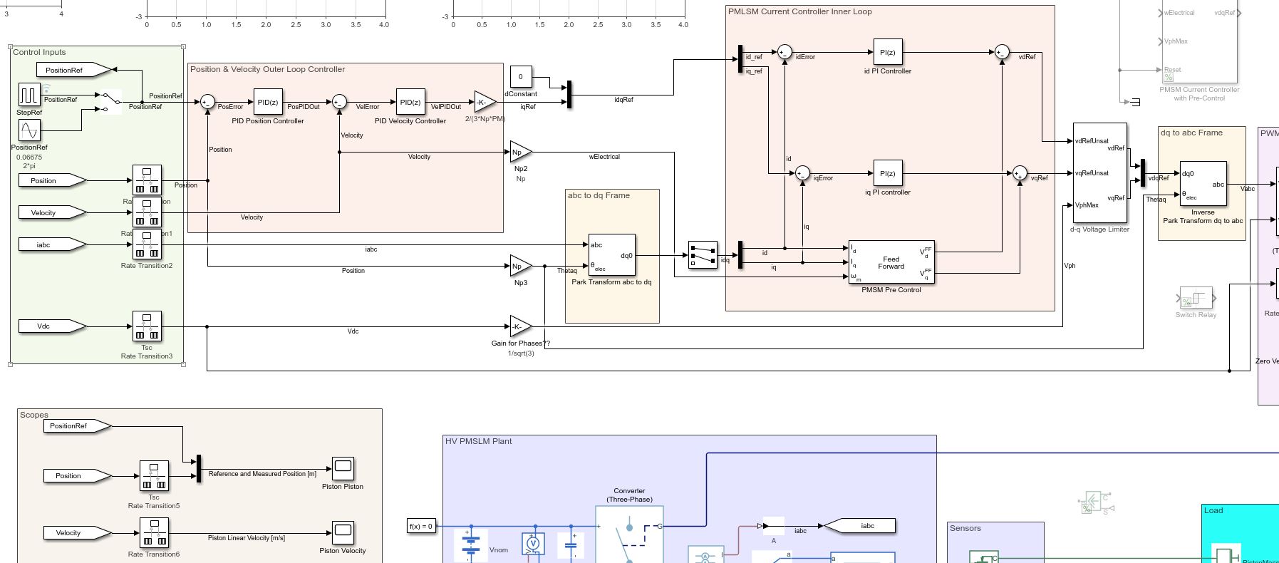
. Again a little stuck on the layout, whether we need to add the pre-controller, and its parameters, have added one for now. Can you have a look if my layout for the PMSM current controller is correct? If so, do i need to identify the model as the next step? Then use the Autotune blocks once i have identified a model as you suggested.
Thanks again
Patrick
The structure looks fine and similar to the one in this example that had the preconroller as well: https://www.mathworks.com/help/slcontrol/ug/tune-field-oriented-controllers-for-a-pmsm-using-closed-loop-pid-autotuner-block.html
I would suggest to go through this example and really master it, and then apply the same principle to your case. It should be fairly similar.
Thanks for your help in getting this far Vasco.
There is very limited resources in the literature available for FOC design with regards to PMLSM to help this project.
Is there additional support from the MathWorks team that built and designed the ee_pmlsm_drive.slx model?
Thanks
Hi All,
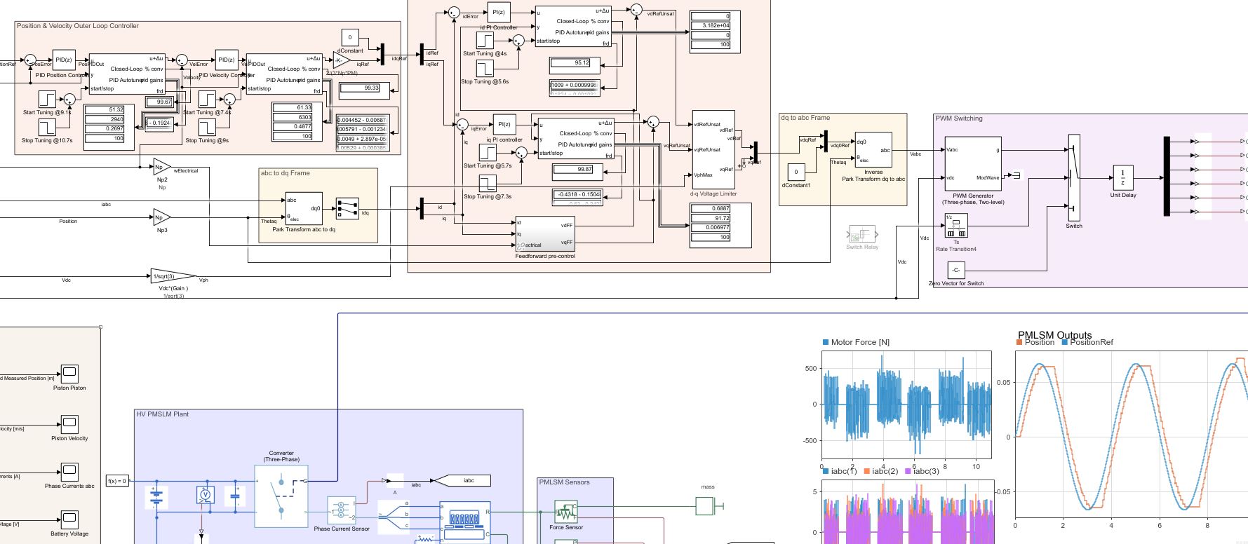
With regards to using the closed-loop PID Auto-tuner blocks for FOC PMSM controller tuning, i have added the tuning blocks to the PMLSM model, see below image of experiment results.
Have a few questions regarding the closed loop auto-tuner experiment set-up, and what bandwidth to use that will best describe my system.
My PMLSM will operate between rest and increase in frequency to approx 20 hz (126rads/s) which is the expected steady state operating frequency during motoring.
For now, i will assume that position tracking accuracy from 1 hz to the steady state operating frequency is neglected.
With a position reference amplitude of 0.0665 meters (total nominal translator stroke of 0.133 meters). Accurate and robust Position tracking with the minimum phase margin is required at this operating point.
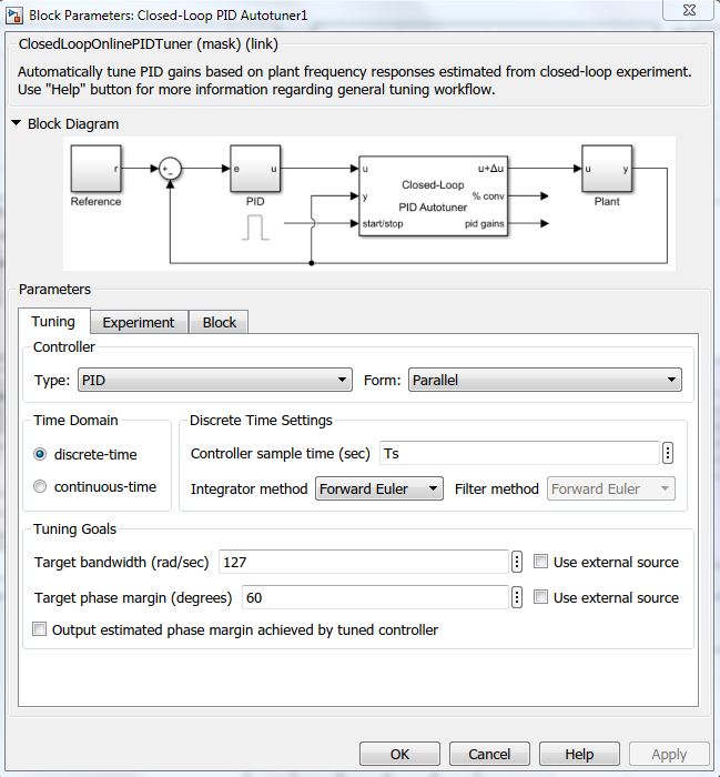
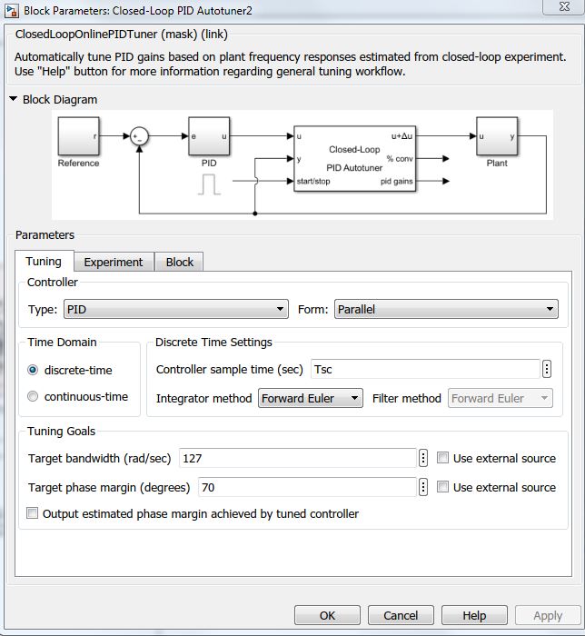
My current experiment setup is as follows: Tsc = 0.001 seconds Inner loop PID Autotuner: Bandwidth 127 rad/s, 60% phase, perturb sine wave amplitude 0.07
Outer loop PID Autotuner: Bandwidth 127 rad/s, 70% phase, perturb sine wave amplitude 0.07
Time for both inner and outer loop experiments to converge is based on 200/bandwidth, which is approx 1.6 seconds
Running the experiment in "normal mode", with the original PID values from ee_pmlsm_drive_data.m.
These values give a slow transient response, and can track in input position reference of approx 0.25 Hz. The experiment position reference has an amplitude of 0.0665 with a frequency of 0.25 hz (1.6 rads/s).
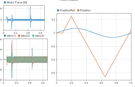
Updating the inner and outer loop PID values with the auto-tuner experiment values shows poor response and lack of reference tracking, see below image, with a position reference frequency of only 1 hz.
Would appreciate any help with how to set up the experiment parameters for a predicted operating frequency of 20 hz
Thanks in advance
Patrick
hi Patrick! nice to see the progress! TLDR; So in short increase inner loop sampling time, and try the clsoed loop autotuning. If it doesn't work, check for convergence to see if actually converged. If not, you need a better starting PID control for the closed loop to work - try with open-loop autotuner
Extended: If I understand correctly you have all the PID working at the same sampling time of 0.001 Ts. This is not how cascading control should be setup - the inner loop should always sample faster than the outer loop. A rule of thumb would be 10x faster.
Now a couple of observation: - are you launching the experiment separately? Is not possible to launch all experiment at the same time. - start with the inner (current) loop. What is the convergency after the experiment? You could setup a small feedback loop in which you stop the experiment when convergency is 99%+, instead of just using the rule of thumb of 200/bandwidth
- The Closed loop autotuning works best if there is a good controller to start with, and you want to refine it. If you believe what you have is not good enough, swap the closed loop autotuning (at best with variant subsystems) to do the experiment using the open-loop autoatuning. This works if no working controller exist and gives you a first solid, but not optimal PID. Then you can use the closed-loop autotuning to refine the PID controller found with open-loop autotuning.
https://www.mathworks.com/help/slcontrol/ug/when-to-use-pid-autotuning.html
But not use open-loop autotuning if the plant has more than one integrator - I'm not sure that's the case for you. Here an example of open-loop autotuner: https://www.mathworks.com/help/slcontrol/ug/tune-pid-controller-in-real-time-using-open-loop-pid-autotuner-block.html
Hi Vasco,
Thanks for your reply. I was using the sample times from the original ee_pmlsm_drive.slx model.
However after your comment,checked the model, i did forget to change the inner loop PID's and auto-tuner PID block sample times to the quicker Ts of 0.00005 s, have rectified.
Outer loop Tsc = 0.001 s Inner Loop Ts = 0.00005 s
Also i have increased the experiment time of the outer loop position auto-tuner block, to allow for convergence, all PID auto-tuner blocks show good convergence, however the position PID seems to be more erratic before it converges to approx 99%, see below screen grab from experiment, showing the experiment times for each PID auto-tuner block, approx 1.6 seconds, except position block which i doubled to 3.2 seconds.

I run the experiment 4 seconds into the simulation, using a slow position ref signal of 0.25 Hz (as the original PID values allow decent tracking on this slow reference signal). Any reference signal faster than 1 Hz diverges and the phase margin increases.
Updating the model with the new PID auto-tuner block values, still shows there is no reference tracking, as before.
My thinking is my bandwidth i have chosen for the inner and outer loop experiment is incorrect, my steady state operating frequency is approx 20 Hz (127 rads/s). Is the bandwidth a function of the loop sample time as well as expected operating frequency?
Inner Loop Experiment values
Outer Loop Experiment values
Thanks again
Hello Patrick,
I need your help. I cannot find ee_pmlsm_drive.slx model. Can you send me a copy? my email is chasingdream1994@gmail.com。
Thanks in advance
Apathy
Hi Patrick, I don't think I can help you further, I'm sorry. The only things that it comes to mind is to try to first get good controller for the internal loop, and once they are good, try to do the experiment for the outer loop - and not try to tune all the loop in one simulations. Just try to focuse to get the Iq and Id well tuned.