Creation, Validation, and Testing of User Defined Trellis Structure
Create User Defined Trellis Structure
This example demonstrates creation of a nonstandard trellis structure for a convolutional encoder with uncoded bits and feedback. The encoder cannot be created using poly2trellis because the peculiar specifications for the encoder do not match the input requirements of poly2trellis.
You can manually create the trellis structure, and then use it as the input trellis structure for an encoder and decoder. The Convolutional Encoder and Viterbi Decoder blocks used in the Convolutional Encoder with Uncoded Bits and Feedback model load the trellis structure created here using a PreLoadFcn callback.
Convolutional Encoder
Create a rate 3/4 convolutional encoder with feedback connection whose MSB bit remains uncoded.

Declare variables according to the specifications.
K = 3;
N = 4;
constraintLength = 4;
Create trellis structure
A trellis structure has the following fields:
numInputSymbols– Number of input symbolsnumOutputSymbols– Number of output symbolsnumStates– Number of statesnextStates– Next state matrixoutputs– Output matrix
For more information about these structure fields, see istrellis.
Reset any previous occurrence of myTrellis structure.
clear myTrellis;Define the trellis structure fields.
myTrellis.numInputSymbols = 2^K;
myTrellis.numOutputSymbols = 2^N;
myTrellis.numStates  = 2^(constraintLength-1);
Create nextStates Matrix
The nextStates matrix is a [numStates x numInputSymbols] matrix. The (i,j) element of the next state matrix is the resulting final state index that corresponds to a transition from the initial state i for an input equal to j.
myTrellis.nextStates = [0  1  2  3  0  1  2  3; ...
                        6  7  4  5  6  7  4  5; ...
                        1  0  3  2  1  0  3  2; ...
                        7  6  5  4  7  6  5  4; ...
                        2  3  0  1  2  3  0  1; ...
                        4  5  6  7  4  5  6  7; ...
                        3  2  1  0  3  2  1  0; ...
                        5  4  7  6  5  4  7  6]
myTrellis = struct with fields:
     numInputSymbols: 8
    numOutputSymbols: 16
           numStates: 8
          nextStates: [8×8 double]
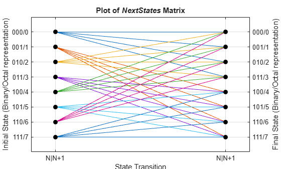
Plot nextStates Matrix
Use the commcnv_plotnextstates helper function to plot the nextStates matrix to illustrate the branch transitions between different states for a given input.
commcnv_plotnextstates(myTrellis.nextStates);
Create outputs Matrix
The outputs matrix is a [numStates x numInputSymbols] matrix. The (i,j) element of the output matrix is the output symbol in octal format given a current state i for an input equal to j.
outputs =  [0  2  4  6  10  12  14  16; ...
            1  3  5  7  11  13  15  17; ...
            0  2  4  6  10  12  14  16; ...
            1  3  5  7  11  13  15  17; ...
            0  2  4  6  10  12  14  16; ...
            1  3  5  7  11  13  15  17; ...
            0  2  4  6  10  12  14  16; ...
            1  3  5  7  11  13  15  17]
outputs = 8×8

     0     2     4     6    10    12    14    16
     1     3     5     7    11    13    15    17
     0     2     4     6    10    12    14    16
     1     3     5     7    11    13    15    17
     0     2     4     6    10    12    14    16
     1     3     5     7    11    13    15    17
     0     2     4     6    10    12    14    16
     1     3     5     7    11    13    15    17
Use oct2dec to display these values in decimal format.
outputs_dec = oct2dec(outputs)
outputs_dec = 8×8

     0     2     4     6     8    10    12    14
     1     3     5     7     9    11    13    15
     0     2     4     6     8    10    12    14
     1     3     5     7     9    11    13    15
     0     2     4     6     8    10    12    14
     1     3     5     7     9    11    13    15
     0     2     4     6     8    10    12    14
     1     3     5     7     9    11    13    15
Copy outputs matrix into the myTrellis structure.
myTrellis.outputs = outputs
myTrellis = struct with fields:
     numInputSymbols: 8
    numOutputSymbols: 16
           numStates: 8
          nextStates: [8×8 double]
             outputs: [8×8 double]
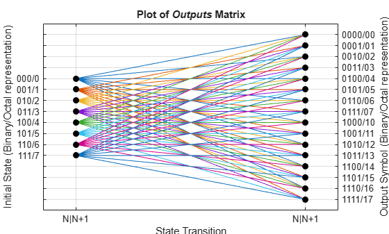
Plot outputs Matrix
Use the commcnv_plotoutputs helper function to plot the outputs matrix to illustrate the possible output symbols for a given state depending on the input symbol.
commcnv_plotoutputs(myTrellis.outputs, myTrellis.numOutputSymbols);
Check Resulting Trellis Structure
istrellis(myTrellis)
ans = logical
   1
A return value of 1 confirms the trellis structure is valid.
Convolutional Encoder with Uncoded Bits and Feedback
The model serves as a unit test bench for the convolutional code implemented. The model shows how to define and use a trellis that describes a convolutional code. The particular code in this example cannot be described by a set of generator and feedback connection polynomials. The code's trellis cannot be created by the poly2trellis because that function expects generator and feedback connection polynomials as input arguments.
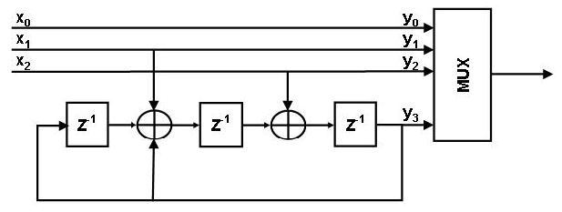
Structure of the Convolutional Code
This figure shows the convolutional code.
Explore Model
The major components of the slex_commcnvencoder model include:
A transmit path that builds a representation of the convolutional encoder using discrete low-level delay and sum (XOR) blocks. This representation looks very similar to the figure showing the structure of the convolutional code.
A transmit-receive path that builds a representation of the same convolutional encoder using the Convolutional Encoder block with the encoder described within the
Trellis structureparameter. This portion of the model also includes the Viterbi Decoder block, which decodes the convolutional code.Both paths compute the number of bit errors.
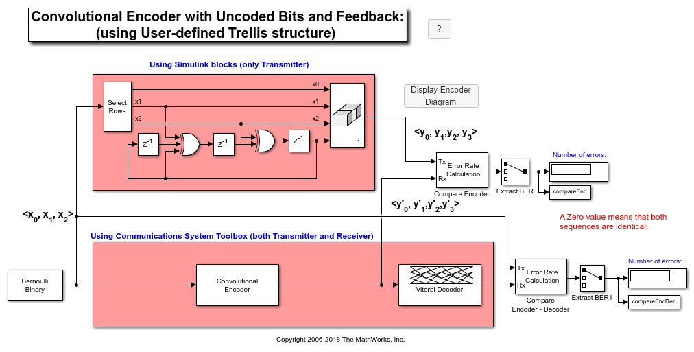
Results and Displays
When you run the simulation, the block labeled Compare Encoder checks that the two representations of the encoder yield the same result. The block labeled Compare Encoder - Decoder checks that the encoder and decoder work properly as a pair. Each Display block in the model shows an error rate of zero, as expected.
Error rate for Compare Encoder signal: 0.000
Error rate for Compare Encoder-Decoder signal: 0.000