fdesign
Filter design specification object
Syntax
Description
Use the fdesign function to create a filter design
specification object that contains the specifications for a filter, such as passband ripple,
stopband attenuation, and filter order. Then, use the design function to design the filter from the filter design specifications
object. For an example, see Design of Lowpass Decimator.
Here is the workflow diagram that shows the simple procedure to design, analyze, and finally apply the filter on streaming data.

For more control options, see Filter Design Procedure. For a complete workflow, see Design a Filter in Fdesign — Process Overview.
designSpecs = fdesign.responseresponse
designSpecs = fdesign.response(spec)fdesign
object.
designSpecs = fdesign.response(___,Fs)
designSpecs = fdesign.response(___,magunits)
Examples
Design a 100-tap FIR lowpass decimator filter that reduces the sample rate of a signal from 60 kHz to 20 kHz. The passband of the filter extends up to 6 kHz. Specify a passband ripple of 0.01 dB and a stopband attenuation of 100 dB.
Fs = 60e3;
N = 99;
Fpass = 6e3;
Apass = 0.01;
Astop = 100;
M = Fs/20e3;
Setup the filter design specifications object using the fdesign.decimator function.
filtSpecs = fdesign.decimator(M,'lowpass','N,Fp,Ap,Ast',N,Fpass,Apass,Astop,Fs);
Design the FIR lowpass decimator using the design function.
The resulting filter is a dsp.FIRDecimator System object™. For details on how to apply this filter to streaming data, refer to dsp.FIRDecimator.
decimFIR = design(filtSpecs,'SystemObject',true)decimFIR =
dsp.FIRDecimator with properties:
Main
DecimationFactor: 3
NumeratorSource: 'Property'
Numerator: [-1.5100e-05 -2.2164e-05 -9.6058e-06 4.3636e-05 1.3739e-04 2.3440e-04 2.6375e-04 1.5609e-04 -9.9524e-05 -4.1180e-04 -5.9905e-04 -4.7613e-04 1.3485e-05 6.9877e-04 0.0012 0.0011 2.8750e-04 -0.0010 -0.0021 -0.0022 … ] (1×100 double)
Structure: 'Direct form'
Show all properties
Use info to display information about the filter.
info(decimFIR)
ans = 11×56 char array
    'Discrete-Time FIR Multirate Filter (real)               '
    '-----------------------------------------               '
    'Filter Structure   : Direct-Form FIR Polyphase Decimator'
    'Decimation Factor  : 3                                  '
    'Polyphase Length   : 34                                 '
    'Filter Length      : 100                                '
    'Stable             : Yes                                '
    'Linear Phase       : Yes (Type 2)                       '
    '                                                        '
    'Arithmetic         : double                             '
    'Input sample rate : 60000                               '
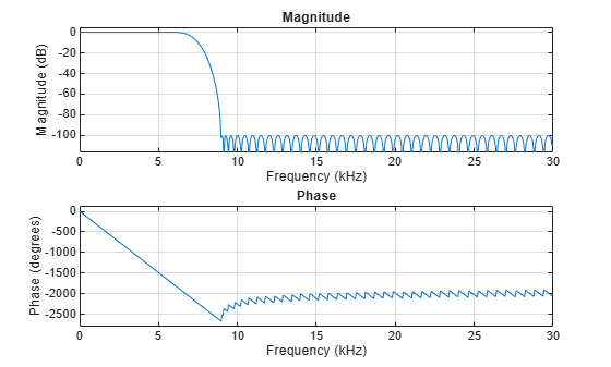
Visualize the frequency response of the filter.
freqz(decimFIR,[],Fs)
Design a lowpass filter to use on a signal sampled at 96 kHz. The passband of the filter extends up to 20 kHz. The stopband of the filter starts at 24 kHz. Specify a passband ripple of 0.01 dB and a stopband attenuation of 80 dB. Determine automatically the order required to meet the specifications.
Set up the filter design specifications object using the fdesign.lowpass function.
Fs = 96e3;
Fpass = 20e3;
Fstop = 24e3;
Apass = 0.01;
Astop = 80;

filtSpecs = fdesign.lowpass(Fpass,Fstop,Apass,Astop,Fs);
Determine the available design algorithms using the designmethods function.
designmethods(filtSpecs,SystemObject=true)
Design Methods that support System objects for class fdesign.lowpass (Fp,Fst,Ap,Ast):


butter
cheby1
cheby2
ellip
equiripple
ifir
kaiserwin
multistage
Using the design function, design an equiripple FIR filter and an elliptic IIR filter that meet the specifications.
lpFIR = design(filtSpecs,'equiripple',SystemObject=true)lpFIR =
dsp.FIRFilter with properties:
Structure: 'Direct form'
NumeratorSource: 'Property'
Numerator: [1.0908e-04 2.1016e-05 -2.3369e-04 -2.8798e-04 9.0899e-05 3.6470e-04 -5.3240e-05 -5.8338e-04 -1.6344e-04 7.4544e-04 4.8812e-04 -8.4772e-04 -9.5828e-04 7.9705e-04 0.0015 -5.2252e-04 -0.0022 -4.9607e-05 0.0028 … ] (1×101 double)
InitialConditions: 0
Show all properties
lpIIR = design(filtSpecs,'ellip',SystemObject=true)lpIIR =
dsp.SOSFilter with properties:
Structure: 'Direct form II'
CoefficientSource: 'Property'
Numerator: [5×3 double]
Denominator: [5×3 double]
HasScaleValues: true
ScaleValues: [0.8017 0.7532 0.7030 1.2976 0.0087 1]
Show all properties
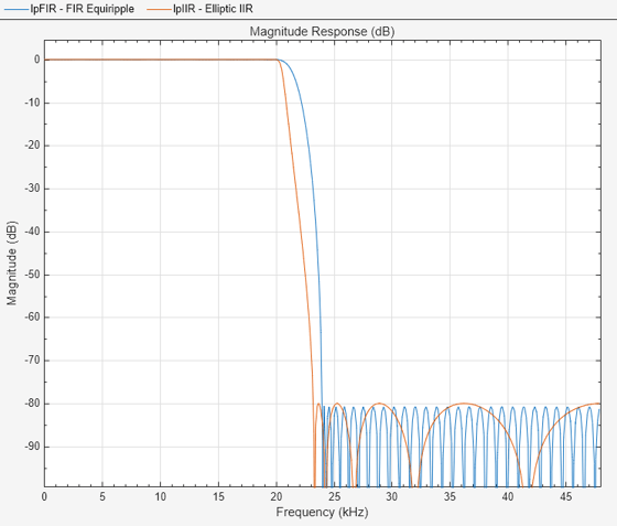
You can also measure the designs to verify that the filters satisfy the constraints.
FIRmeas = measure(lpFIR)
FIRmeas =
Sample Rate      : 96 kHz
Passband Edge    : 20 kHz
3-dB Point       : 21.4297 kHz
6-dB Point       : 21.8447 kHz
Stopband Edge    : 24 kHz
Passband Ripple  : 0.0092309 dB
Stopband Atten.  : 80.6014 dB
Transition Width : 4 kHz
IIRmeas = measure(lpIIR)
IIRmeas =
Sample Rate      : 96 kHz
Passband Edge    : 20 kHz
3-dB Point       : 20.5524 kHz
6-dB Point       : 20.7138 kHz
Stopband Edge    : 24 kHz
Passband Ripple  : 0.01 dB
Stopband Atten.  : 80 dB
Transition Width : 4 kHz
Estimate and display the computational cost of each filter. The equiripple FIR filter requires many more coefficients than the elliptic IIR filter.
FIRcost = cost(lpFIR)
FIRcost = struct with fields:
                  NumCoefficients: 101
                        NumStates: 100
    MultiplicationsPerInputSample: 101
          AdditionsPerInputSample: 100
IIRcost = cost(lpIIR)
IIRcost = struct with fields:
                  NumCoefficients: 20
                        NumStates: 10
    MultiplicationsPerInputSample: 20
          AdditionsPerInputSample: 20
Use filterAnalyzer function to visualize the resulting designs and compare their properties.
hvft = filterAnalyzer(lpFIR,lpIIR,SampleRates=Fs);
setLegendStrings(hvft,["FIR Equiripple","Elliptic IIR"])
Design a lowpass Butterworth filter that has a passband edge frequency of rad/sample, a stopband frequency of rad/sample, a passband ripple of 1 dB, and a stopband attenuation of 80 dB.
Create a lowpass filter design specification object using the fdesign.lowpass function. Specify the design parameters.
lowpassSpecs = fdesign.lowpass(0.4,0.5,1,80);
To view a list of design methods available for the specification object, use the designmethods function. If multiple methods are available, pick one that best meets the design criteria. For this example, pick 'butter'.
designmethods(lowpassSpecs,SystemObject=true)
Design Methods that support System objects for class fdesign.lowpass (Fp,Fst,Ap,Ast):


butter
cheby1
cheby2
ellip
equiripple
ifir
kaiserwin
multistage
Furthermore, you can specify the design options used in designing the filter. To see a list of available options, run the designoptions function on lowpassSpecs. The design options are dependent on the design method you pick. The design method, in this case, 'butter', must be specified as an argument to the designoptions function.
designoptions(lowpassSpecs,"butter",Systemobject=true)ans = struct with fields:
FilterStructure: {'df1sos' 'df2sos' 'df1tsos' 'df2tsos' 'cascadeallpass' 'cascadewdfallpass'}
SOSScaleNorm: 'ustring'
SOSScaleOpts: 'fdopts.sosscaling'
MatchExactly: {'passband' 'stopband'}
DefaultFilterStructure: 'df2sos'
DefaultMatchExactly: 'stopband'
DefaultSOSScaleNorm: ''
DefaultSOSScaleOpts: [1×1 fdopts.sosscaling]
The filter order necessary to meet a set of design constraints must also be rounded up to an integer value. This loosens some of the constraints, and as a consequence, some design specifications are met while others are exceeded. The 'MatchExactly' option allows you to match the passband or stopband exactly while exceeding the specification for the other band. Design the filter so that it matches the passband exactly.
The resulting filter is a dsp.SOSFiter System object™. For details on how to apply this filter on streaming data, refer to dsp.SOSFilter.
IIRbutter = design(lowpassSpecs,"butter",MatchExactly="passband", ...
    SystemObject=true)
IIRbutter =
  dsp.SOSFilter with properties:

            Structure: 'Direct form II'
    CoefficientSource: 'Property'
            Numerator: [16×3 double]
          Denominator: [16×3 double]
       HasScaleValues: true
          ScaleValues: [0.3390 0.3104 0.2866 0.2667 0.2500 0.2359 0.2241 0.2142 0.2059 0.1990 0.1935 0.1891 0.1858 0.1834 0.1820 0.4261 1]

  Show all properties
Visualize the magnitude response of the filter.
filterAnalyzer(IIRbutter)

Input Arguments
Output Arguments
More About
Here is the workflow diagram of the overall procedure for designing and analyzing the filter.

Here are the steps in detail:
Create an
fdesign.specification object to specify the design parameters.responseUse
designmethodsto determine the filter design methods that work for your new filter specification object. If you choose to use the default design method, then this step is optional.If you prefer to change the design options and would like to see a list of available options, run the
designoptionsfunction on the specification object. The output also shows the design options the filter uses by default.Use
designto design the filter from the filter specification object. Specify the design method (determined from step 2) as an input. If the design options must change from the default values, specify them as name-value pairs following the design method.Further analysis, such as viewing the frequency response of the filter, computing the cost of implementing the filter, and measuring the filter response characteristics, can be done using one of the supported Analysis Functions for Filter System Objects.
Once you analyze the filter and determine that the filter satisfies the design constraints, you can apply the filter object to streaming input data. For details on how to pass data to the filter object, refer to the corresponding filter System object™ reference pages.
For a detailed example on the design and analysis, see Lowpass Butterworth Filter Specification and Design.
Version History
Introduced in R2009a