dsphdl.Channelizer
Polyphase filter bank and fast Fourier transform
Description
The dsphdl.Channelizer
System object™ separates a broadband input signal into multiple narrowband output signals. It
provides hardware speed and area optimization for streaming data applications. The object
accepts scalar or vector input of real or complex data, provides hardware-friendly control
signals, and has optional output frame control signals. You can achieve gigasamples-per-second
(GSPS) throughput by using vector input. The object implements a polyphase filter, with one
subfilter per input vector element. The hardware implementation interleaves the subfilters,
which results in sharing each filter multiplier (FFT Length /
Input Size) times. The object implements the same pipelined Radix 2^2 FFT
algorithm as the dsphdl.FFT
System object.
To channelize input data:
Create the
dsphdl.Channelizerobject and set its properties.Call the object with arguments, as if it were a function.
To learn more about how System objects work, see What Are System Objects?
Note
The output of this object has a phase shift compared to the dsp.Channelizer (DSP System Toolbox™) object unless you set the PreservePhase property to
true. The channels detected by both blocks match when analyzed over
multiple frames. Also, to match the dsp.Channelizer (DSP System Toolbox) object, apply FFT Length – 1 zeros at the start of the
data stream. For an example of comparing the two algorithms, see Preserve Channelizer Phase.
Note
You can also generate HDL code for this hardware-optimized algorithm, without creating a MATLAB® script, by using the DSP HDL IP Designer app. The app provides the same interface and configuration options as the System object.
Creation
Description
channelizer = dsphdl.Channelizerchannelizer, that implements a raised-cosine filter
and an 8-point FFT.
channelizer = dsphdl.Channelizer(PropertyName=Value)
Properties
Usage
Syntax
Description
[ filters
and computes a fast Fourier transform, and returns the frequency channels,
dataOut,validOut]
= channelizer(dataIn,validIn)dataOut, detected in the input signal, dataIn,
when validIn is 1 (true). The
validIn and validOut arguments are logical
scalars that indicate the validity of the input and output signals, respectively.
[
returns the frequency channels, dataOut,validOut]
= channelizer(dataIn,validIn,reset)dataOut, detected in the input
signal, dataIn, when validIn is
1 (true) and reset is 0
(false). When reset is 1 (true), the object stops
the current calculation and clears all internal state.
To use this syntax, set the ResetInputPort property to true. For example:
channelizer = dsphdl.Channelizer(...,ResetInputPort=true);
...
[dataOut,validOut] = channelizer(dataIn,validIn,reset)
[ returns the frequency channels,
dataOut,startOut,endOut,validOut]
= channelizer(___)dataOut, computed from the input arguments of any of the previous
syntaxes. startOut is 1 (true) for the first
sample of a frame of output data. endOut is 1
(true) for the last sample of a frame of output data.
To use this syntax, set the StartOutputPort and EndOutputPort
properties to true. For example:
channelizer = dsphdl.Channelizer(...,StartOutputPort=true,EndOutputPort=true);
...
[dataOut,startOut,endOut,validOut] = channelizer(dataIn,validIn)
Input Arguments
Output Arguments
Object Functions
To use an object function, specify the
System object as the first input argument. For
example, to release system resources of a System object named obj, use
this syntax:
release(obj)
Examples
Create a function that contains a channelizer object and supports HDL code generation.
Create the specifications and input signal. The signal has 8 frequency channels.
N = 8;
loopCount = 1024;
offsets = [-40 -30 -20 10 15 25 35 -15];
sinewave = dsp.SineWave(ComplexOutput=true, ...
    Frequency=offsets+(-375:125:500), ...
    SamplesPerFrame=loopCount);
sa = spectrumAnalyzer(ShowLegend=true, ...
     SampleRate=sinewave.SampleRate/N);
Write a function that creates and calls the channelizer System object™. You can generate HDL from this function.
function [yOut,validOut] = HDLChannelizer8(yIn,validIn)
%HDLChannelizer8
% Process one sample of data using the dsphdl.Channelizer System object
% yIn is a fixed-point scalar or column vector.
% validIn is a logical scalar value.
% You can generate HDL code from this function.

  persistent channelize8;
  coder.extrinsic('tf');
  coder.extrinsic('dsp.Channelizer');

  if isempty(channelize8)
    % Use filter coeffs from non-HDL channelizer, or supply your own.
    channelizer = coder.const(dsp.Channelizer(NumFrequencyBands=8));
    coeff = coder.const(tf(channelizer));
    channelize8 = dsphdl.Channelizer(NumFrequencyBands=8,FilterCoefficients=coeff);
  end
  [yOut,validOut] = channelize8(yIn,validIn);
end

% Copyright 2016-2023 The MathWorks, Inc.
Channelize the input data by calling the object for each data sample.
y = zeros(loopCount/N,N);
validOut = false(loopCount/N,1);
yValid = zeros(loopCount/(N*N),N);
for reps=1:10
   x = fi(sum(sinewave(),2),1,18);
   for loop=1:length(x)
      [y(loop,:),validOut(loop)]= HDLChannelizer8(x(loop),true);
   end
   yValid = y(validOut == 1,:);
   sa(yValid);
end
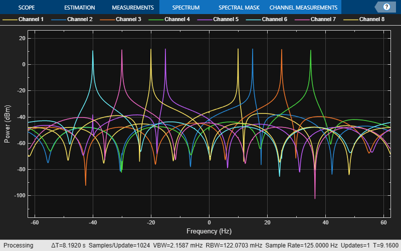
This example shows how to separate channels of a sine wave signal with multiple frequencies, and compare the results using dsp.Channelizer and dsphdl.Channelizer objects.
You can also implement this algorithm in Simulink® by using the DSP HDL Toolbox™ Channelizer block.
Generate a sine wave with multiple frequencies as the input signal. Configure both channelizers to split the signal into 8 frequency bands.
Fs = 2000;
nBand = 8;

nTone = 3; % # of tones at randomized freq
tones = randi([-Fs/2 Fs/2],1,nTone)
tones = 1×3
630 812 -746
sinewave = dsp.SineWave(ComplexOutput=true,Frequency=tones,SampleRate=Fs,...
    SamplesPerFrame=100*nBand);
DSP System Toolbox™ Channelizer
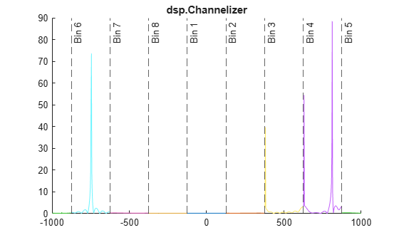
Split the input signal into frequency channels by using the dsp.Channelizer System object™. Calculate and display the magnitude of the frequency response.
channelizer = dsp.Channelizer(NumFrequencyBands=nBand,StopbandAttenuation=140);

x = sum(sinewave(),2);
y = channelizer(x);
yf = abs(fftshift(fft(y),1));

% Frequency axis
Finc = Fs/numel(yf);
Faxis = -Fs/2:Finc:Fs/2-Finc;

% Shift the freq axis so bin 1 is Fs/nBand centered at 0 Hz
Faxis = circshift(Faxis,-numel(yf)/2 + size(yf,1)/2);
Fgrid = reshape(Faxis,size(yf));

% Bin (nBand/2)+1 wraps from Fs/2 to -Fs/2. Nulling the data point at -Fs/2
% prevents a connecting line across the plot
yf(Fgrid==-Fs/2) = NaN;

figure; colororder("glow12")
title("dsp.Channelizer")
hold on;
for n = 1:size(yf,2)
    xline(Fgrid(1,n),'--',['Bin ' num2str(n)]);
    plot(Fgrid(:,n),yf(:,n));

end
hold off
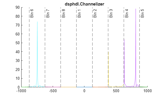
DSP HDL Toolbox™ Channelizer
The dsphdl.Channelizer System object™ uses a different architecture compared to the DSP System Toolbox version. The hardware-optimized implementation results in a phase shift in the output. However the magnitude responses are the same.
hdlchannelizer = dsphdl.Channelizer(NumFrequencyBands=nBand,...
    FilterCoefficients=channelizer.coeffs.Numerator,Normalize=false);

latency = getLatency(hdlchannelizer)
latency = 53
xin = [x; zeros(latency,1)]; % account for HDL latency
vin = [true(numel(x),1); false(latency,1)];

z = zeros(numel(xin),nBand);
vout = false(numel(xin),1);
for k = 1:numel(vout)
    [z(k,:),vout(k)] = hdlchannelizer(xin(k),vin(k));
end

zvalid = z(vout,:);
zf = abs(fftshift(fft(zvalid),1));

% Null data point at -F2/2 for plotting
zf(Fgrid==-Fs/2) = NaN;

figure; colororder("glow12")
title("dsphdl.Channelizer")
hold on;
for n = 1:size(zf,2)
    xline(Fgrid(1,n),'--',['Bin ' num2str(n)]);
    plot(Fgrid(:,n),zf(:,n));
end
hold off
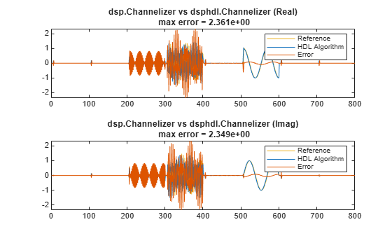
Compare the outputs of the dsp.Channelizer and the dsphdl.Channelizer objects sample-by-sample.
reference=reshape(y,[],1);
dsphdl=reshape(zvalid,[],1);
label = 'dsp.Channelizer vs dsphdl.Channelizer';

ref_vec = double([real(reference) imag(reference)]);
dsphdl_vec = double([real(dsphdl) imag(dsphdl)]);
err_vec = ref_vec - dsphdl_vec;
max_err = max(abs(err_vec));
max_ref = max(abs(ref_vec));

figure;
c = get(groot,'defaultAxesColorOrder');
% Plot real and imaginary parts separately
tag = {'(Real)','(Imag)'};
msg = sprintf('\nMaximum error for %s out of %d values\n',label,length(dsphdl));
for n = 1:size(ref_vec,2)
    msg = [msg sprintf('%s %d (absolute), %d (percentage)\n',tag{n},max_err(n),max_err(n)/max_ref(n)*100)];
    row_num = size(ref_vec,2);
    col_num = 1;
    plot_num = n;
    subplot(row_num,col_num,plot_num);
    plot(ref_vec(:,n),'Color',c(3,:));
    hold on
    plot(dsphdl_vec(:,n),'Color',c(1,:));
    plot(err_vec(:,n),'Color',c(2,:));
    legend('Reference','HDL Algorithm','Error')
    title(sprintf('%s %s\n max error = %.3d',label,tag{n},max_err(n)));
    hold off
end
fprintf(msg);
Maximum error for dsp.Channelizer vs dsphdl.Channelizer out of 800 values
(Real) 2.360518e+00 (absolute), 1.556526e+02 (percentage)
(Imag) 2.348774e+00 (absolute), 1.511404e+02 (percentage)
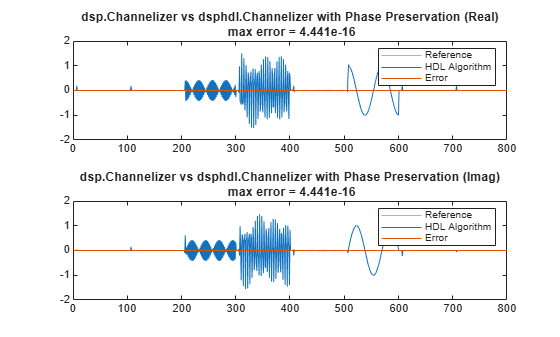
To produce identical outputs, zero-pad the input with nBand-1 zeros, and configure the dsphdl.Channelizer object to adjust the output phase. The phase correction adds five cycles of latency to the object compared to the default settings. If your output size is the same as the FFT length, the channelizer implements the phase correction with canonical signed digit (CSD) multiplies. Otherwise, the phase correction uses one complex multiplier.
reset(hdlchannelizer);
release(hdlchannelizer);
hdlchannelizer.PreservePhase=true;
latency = getLatency(hdlchannelizer)
latency =
58
xin2 = [zeros(nBand-1,1); xin];
vin2 = [true(nBand-1,1); vin];

z2 = zeros(numel(xin2),nBand);
vout2 = false(numel(xin2),1);
for k = 1:numel(vout2)
    [z2(k,:),vout2(k)] = hdlchannelizer(xin2(k),vin2(k));
end
z2valid = z2(vout2,:);
Again, compare the outputs of the dsp.Channelizer and the dsphdl.Channelizer objects sample-by-sample.
reference=reshape(y,[],1);
dsphdl=reshape(z2valid,[],1);
label = 'dsp.Channelizer vs dsphdl.Channelizer with Phase Preservation';

ref_vec = double([real(reference) imag(reference)]);
dsphdl_vec = double([real(dsphdl) imag(dsphdl)]);
err_vec = ref_vec - dsphdl_vec;
max_err = max(abs(err_vec));
max_ref = max(abs(ref_vec));

figure;
c = get(groot,'defaultAxesColorOrder');
% Plot real and imaginary parts separately
tag = {'(Real)','(Imag)'};
msg = sprintf('\nMaximum error for %s out of %d values\n',label,length(dsphdl));
for n = 1:size(ref_vec,2)
    msg = [msg sprintf('%s %d (absolute), %d (percentage)\n',tag{n},max_err(n),max_err(n)/max_ref(n)*100)];
    row_num = size(ref_vec,2);
    col_num = 1;
    plot_num = n;
    subplot(row_num,col_num,plot_num);
    plot(ref_vec(:,n),'Color',c(3,:));
    hold on
    plot(dsphdl_vec(:,n),'Color',c(1,:));
    plot(err_vec(:,n),'Color',c(2,:));
    legend('Reference','HDL Algorithm','Error')
    title(sprintf('%s %s\n max error = %.3d',label,tag{n},max_err(n)));
    hold off
end
fprintf(msg);
Maximum error for dsp.Channelizer vs dsphdl.Channelizer with Phase Preservation out of 800 values
(Real) 4.440892e-16 (absolute), 2.928324e-14 (percentage)
(Imag) 4.440892e-16 (absolute), 2.857653e-14 (percentage)
The latency of the dsphdl.Channelizer object varies with the FFT length, filter structure, vector size, and input type. Use the getLatency function to find the latency of a particular configuration. The latency is measured as the number of cycles between the first valid input and the first valid output, assuming that the input is contiguous. The number of filter coefficients does not affect the latency. Setting the output size equal to the input size reduces the latency because the samples are not saved and reordered.
Create a dsphdl.Channelizer object with filter structure set to direct form transposed and request the latency.
channelize = dsphdl.Channelizer(NumFrequencyBands=512, ...
    FilterStructure='Direct form transposed');
L512 = getLatency(channelize)
L512 =
1118
Request hypothetical latency information about a similar object with a different number of frequency bands (FFT length). The properties of the original object do not change.
L256 = getLatency(channelize,256)
L256 =
592
N = channelize.NumFrequencyBands
N =
512
Request hypothetical latency information of a similar object that accepts eight-sample vector input.
L256v8 = getLatency(channelize,256,8)
L256v8 =
132
Enable scaling at each stage of the FFT. The latency does not change.
channelize.Normalize = true;
L512n = getLatency(channelize)
L512n =
1118
Request the same output size and order as the input data. The latency decreases because the object does not need to store and reorder the data before output. The default input size is scalar.
channelize.OutputSize = 'Same as input size';
L512r = getLatency(channelize)
L512r = 1084
Check the latency of a vector input implementation where the input and output are the same size. Specify the current value of the FFT length and a vector size of 8 samples. The latency decreases because the object computes results in parallel when the input is a vector.
L512rv8 = getLatency(channelize,channelize.NumFrequencyBands,8)
L512rv8 =
218
Check the latency of a vector input implementation where the input type is complex. Specify the current value of the FFT length and a vector size of 16 samples.
L512rv16i = getLatency(channelize,channelize.NumFrequencyBands,16,true)
L512rv16i =
152
Algorithms
This object implements the algorithm described on the Channelizer block reference page.
Note
The output of the dsphdl.Channelizer object does not match the output
from the dsp.Channelizer object sample-for-sample. This mismatch is because
the objects apply the input samples to the subfilters in different orders. The
dsphdl.Channelizer object applies input X(0) to subfilter
EM-1(z), X(1) to subfilter
EM-2(z), ...,
X(M-1) to subfilter E0(z).
The channels detected by both objects match, when analyzed over multiple frames.
This diagram shows validIn and validOut signals for
contiguous input data with a vector size of 16, an FFT length of 512, and when you
select the Direct form transposed filter architecture. In this
example, the output vector size is specified same as the input vector size.
The diagram also shows the optional startOut and endOut
signals that indicate frame boundaries. When enabled, startOut pulses for
one cycle with the first validOut of the frame, and
endOut pulses for one cycle with the last validOut
of the frame.
If you apply continuous input frames (no gap in validIn between frames),
the output will also be continuous, after the initial latency.

The validIn signal can be noncontiguous. Data accompanied by a
validIn signal is stored until a frame is filled. Then
the data in output is a contiguous frame of
N/M cycles. This diagram shows
noncontiguous input and contiguous output for an FFT length of 512 and a vector size
of 16 samples.
