Main Content

PWM

R2026b

Generate pulse width modulated waveforms

Since R2022b

  • PWM block

Libraries:
Embedded Coder Support Package for Infineon AURIX TC4x Microcontrollers / AURIX TC4x

Description

Add-On Required: This feature requires the Embedded Coder Support Package for Infineon AURIX TC4x Microcontrollers add-on.

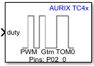
The block input controls the duty cycle of the square waveform for the corresponding channel. An input value of 0 produces a 0 percent duty cycle and an input value of 100 produces a 100 percent duty cycle. It accepts N x 1 values of duty cycles corresponding to the N channels selected.

Examples
Ports

Input

expand all

The value sent to the block input determines the duty cycle of the square wave that the board outputs on the specified PWM pin specified in PWM Peripheral Configuration.

Data Types: Float

The freq port determines the frequency of PWM signal for the selected channels. When you enable the frequency port, the port accepts a scalar input value and sets it as the frequency of the timer unit.

Dependencies

To enable this port, select the Enable frequency input parameter.

The phase port accepts an input value in the range of 0 to 2pi and sets the phase for the corresponding channel. It accepts N x 1 values corresponding to the N channels selected.

Dependencies

To enable this port, select the Enable phase input parameter.

Data Types: single | double

This port accepts the rising dead-time values in seconds as a vector of size N x 1 or N x 1, where N is the configured Number of channels value. For the PWM channels where Enable Dead Time Module is disabled, the corresponding rising dead-time value must be set to zero.

For example, if you set Number of channels to 2 and select Enable Dead Time Module parameter for the first channel, the input vector must be [x 0], where x represents the rising dead-time value of the first channel.

Dependencies

To enable this port, select the Enable dead time properties input parameter.

Data Types: Float | int8 | uint8 | int16 | uint16 | int32 | uint32

This port accepts the falling dead-time values in seconds as a vector of size N x 1 or N x 1, where N is the configured Number of channels value. For the PWM channels where Enable Dead Time Module is disabled, the corresponding rising dead-time value must be set to zero.

For example, if you set Number of channels to 2 and select Enable Dead Time Module parameter for the first channel, the input vector must be [x 0], where x represents the falling dead-time value of the first channel.

Dependencies

To enable this port, select the Enable dead time properties input parameter.

Data Types: Float | int8 | uint8 | int16 | uint16 | int32 | uint32

Output

expand all

The block outputs the status of the PWM module as one of these values:

  • 255—Unknown state

  • 0— Initialized

  • 1— Running

  • 2— Stopped

  • 3— Error

Dependencies

To view this port, select the Enable status output parameter.

Data Types: uint8

The port outputs the PWM bus object in the SoC Blockset™ for AMD simulation message format during simulation. The PWM bus object contains the information received by the block at the input ports.

Dependencies

To view this port, select the Enable simulation port parameter and set the port type to SoC Data (Message based).

The port outputs the PWM bus object during simulation. The PWM bus object contains the information received by the block at the input ports.

Dependencies

To view this port, select the Enable simulation port parameter and set the port type to Signal.

Parameters

expand all

Basic

Select this parameter to set the PWM frequency.

When you select the Enable frequency input parameter, the block configures an input port, freq.

Select this parameter to set the phase of selected channel.

When you select the Enable phase input parameter, the block configures an input port, phase.

When you select the Enable status output parameter, the block configures Status output port.

Select this parameter to enable peripheral simulation capability.

Select this parameter to configure either the SoC compatible or the Simulink® signal based simulation ports to enable peripheral simulation capability.

Dependencies

To view this parameter, select the Enable simulation port parameter.

Advanced

Select the required number of PWM channels to send the duty cycles. The number of channels determines the size of the input ports phase, dtm_rise, and dtm_fall.

The number of channels selected depends on the timer module selection in PWM peripheral configuration app.

  • TOM—16 channels are available

  • ATOM—8 channels are available

Select this parameter to determine the PWM dead time value in seconds.

For more information on standard dead time generation, see Dead-Time Module Properties.

Note

Enabling the dead time properties parameter in the block configures the dtm_rise and dtm_fall input ports. To use the dead time functionality, go to PWM Peripheral Configuration in the Hardware Mapping window and configure the corresponding dead time parameters in Module and Channel tabs.

Version History

Introduced in R2022b