Generate Device Tree for IP Core
Dynamically generate device trees that include nodes for the HDL Coder™ generated IP core by using the HDL Coder IP Core generation workflow. The generated device tree also includes nodes for your board peripherals, reference design IP cores, and reference design interfaces that access the processing system (PS) of your target field programmable gate array (FPGA) or system on a chip (SoC) board. Program your target board with the generated device tree and bitstream.
Get Started with Device Trees
A device tree is a data structure that describes hardware devices to the operating system running on the target board. The operating system kernel uses the device tree description to manage the available hardware devices. For example, the operating system uses the device tree to load the specific device driver for a given hardware device.
The device tree has a tree data structure format consisting of nodes and properties. The image shows these components of a device tree.
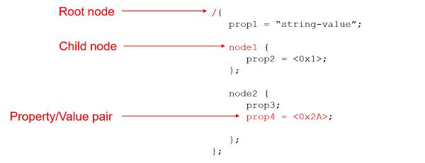
In the device tree:
Nodes represent devices in the system.
Each node has properties specified as property-value pairs that describe the characteristics of the device.
Each node has exactly one parent, except for the root node, which has no parent. The root node is designated by using a forward slash.
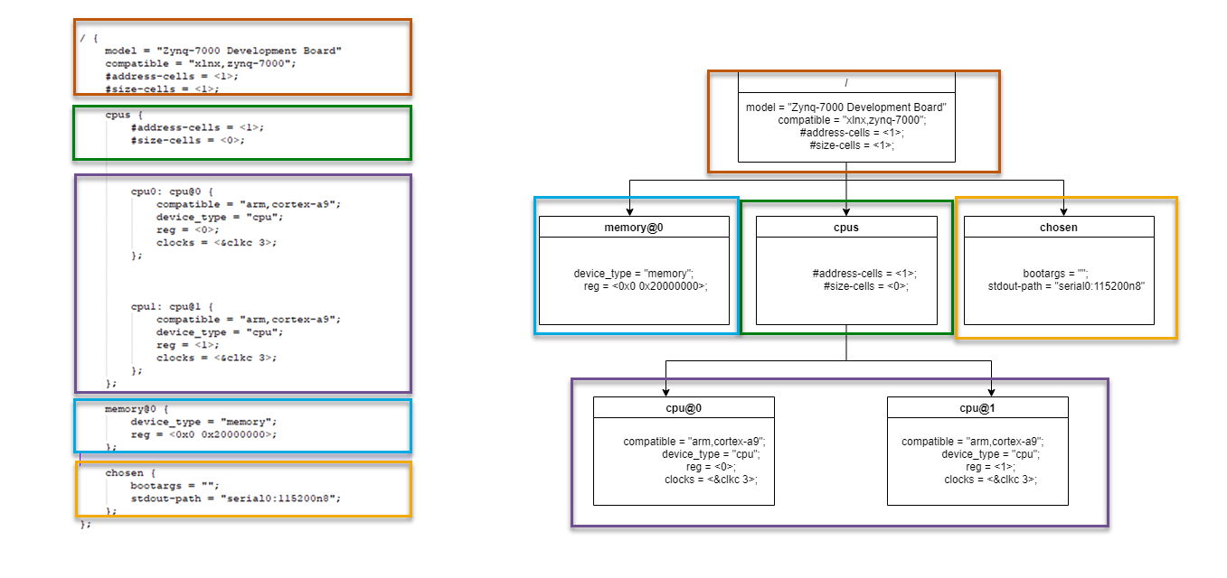
This image shows an example device tree. The left side shows the device tree source file. The right side shows a conceptual diagram of the tree structure with nodes and properties. The names of the boxes represent the node names and the text in the box represents the property-value pairs of the nodes.
Use Device Trees with IP Core Generation Workflow
When you deploy a hardware/software design to a SoC device, the device tree informs the PS about IP cores available in the bitstream. The IP cores appear to the PS as devices, which can be accessed from the software application by using device drivers. Therefore, the device tree and bitstream must be synchronized.
You can generate device tree nodes corresponding to the generated IP core by using the IP core generation workflow. The workflow keeps the device tree and bitstream in sync by updating the device tree whenever your IP core changes.
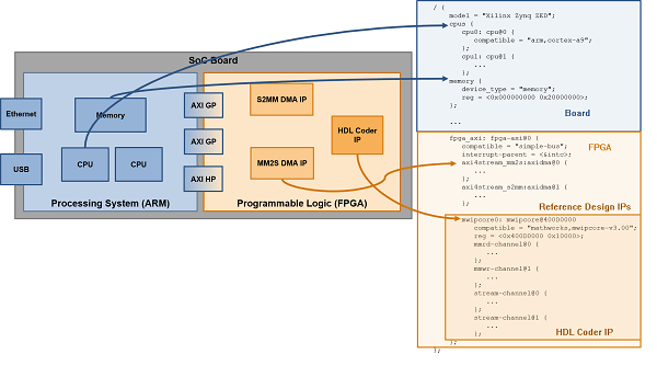
To enable generation of device tree nodes for the HDL Coder generated IP cores, HDL Coder separates the device tree into three distinct segments:
Board segment— Device tree nodes corresponding to fixed hardware on your board, such as the central processing unit (CPU) and processor peripherals. The board device tree is typically obtained from the board vendor.
Reference design segment— Device tree nodes corresponding to IP cores in your reference design. This segment of the device tree is typically created when you author a reference design.
HDL Coder IP Core segment— Device tree nodes corresponding to the IP core generated by HDL Coder. This segment of the device tree does not need to be authored as it can be dynamically generated by HDL Coder.
This image shows an SoC board with its individual device tree segments.
When you deploy your design to the target, HDL Coder automatically combines these segments together into a complete device tree that is used to program the target. These sections walk you through the process of registering and generating the different segments of your device tree.
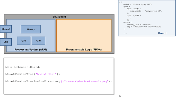
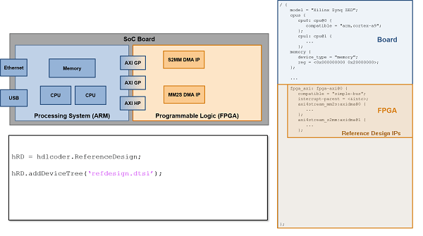
Register Device Tree for Custom Board
Register the board device tree to your custom board design by using the
addDeviceTree and addDeviceTreeIncludeDirectory
methods of the hdlcoder.Board object. For more information, see hdlcoder.Board, addDeviceTree, and addDeviceTreeIncludeDirectory.
This image shows the board device tree registered to your custom board.
Register Device Tree for Custom Reference Design
Register the reference design portion of your device tree when authoring a reference
design by using the addDeviceTree and
addDeviceTreeIncludeDirectory methods of the
hdlcoder.ReferenceDesign object. To register a device tree, your
reference design must contain a processing system IP. Enable the
HasProcessingSystem property of the
hdlcoder.ReferenceDesign object. See hdlcoder.ReferenceDesign, addDeviceTree, and addDeviceTreeIncludeDirectory.
This image shows the reference design for a device tree registered to your custom reference design.
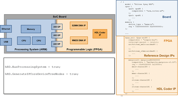
Generate IP Core Device Tree Node
During the IP core generation workflow, HDL Coder generates an IP core and inserts it into your reference design. HDL Coder can also generate corresponding device tree nodes for this IP core and
combine them with the board and reference design device trees. Generate the device tree
node for your IP core by using the HDL Coder IP core generation workflow. Enable the
GenerateIPCoreDeviceTreeNodes property of the
hdlcoder.ReferenceDesign object to generate the device tree nodes for
your IP core. See GenerateIPCoreDeviceTreeNodes.
This image shows the reference design for a device tree when generating and adding device tree nodes is enabled for your IP core.
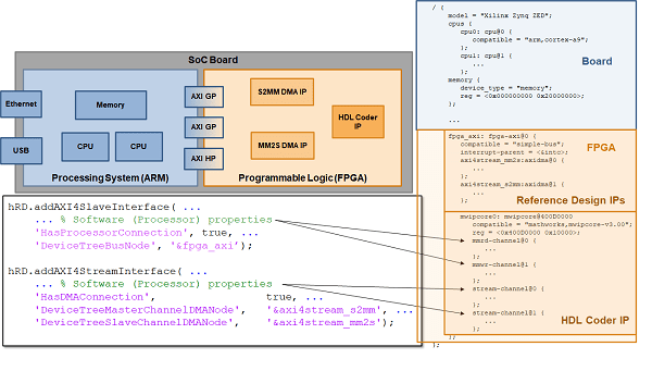
To enable device tree generation for your IP core, you must specify the relevant
information for the reference design interfaces that connect to the processing system.
Enable the generation of device tree nodes by specifying information for the interfaces
that connect to the PS on your target device. Interfaces specify references to other
device tree nodes. To enable device tree generation for the register interface,
enable the HasProcessorConnection property and specify the value for
the DeviceTreeNode property of the
addRegisterInterface method for the
hdlcoder.ReferenceDesign object. See HasProcessorConnection, addRegisterInterface,
and DeviceTreeBusNode. Enable device tree
generation for the AXI4 Stream interface by enabling the HasDMAConnection
and specifying values for the
DeviceTreeMasterChannelDMANode and
DeviceTreeSlaveChannelDMANode. See
addAXI4StreamInterface, DeviceTreeMasterChannelDMANode, DeviceTreeSlaveChannelDMANode, and HasDMAConnection.
This image shows the device tree node generation enabled for the IP Core register, such as AXI4 or AXI4-Lite, and AXI4 stream interfaces.
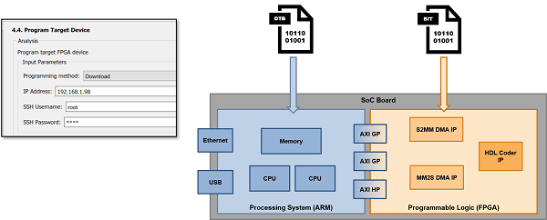
Deploy Device Tree and Bitstream
Download the generated device tree and bitstream for your custom board, reference design, and IP core to the target device by using the HDL Coder IP core generation workflow. The IP core generation workflow compiles the board, reference design, and IP core device trees into a single device tree and then programs them onto the target device along with the generated bitstream. This image shows the generated device tree and bitstream programmed onto the target device.
During the download, HDL Coder uses the device tree compiler on the target board to combine the board device tree, reference design device tree, and IP core device tree. HDL Coder then copies the compiled device tree files back to your host computer.
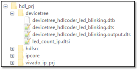
The following device tree files are generated during the IP Core Generation workflow:
devicetree_<model-name>.dtb— The binary device tree file used to program the board. This file is generated by the device tree compiler.devicetree_<model-name>.dts— The source device tree file provided as an input to the device tree compiler. This file is generated by HDL Coder.devicetree_<model-name>.output.dts— A combined source file which contains information for the board device tree, reference design device tree, and your IP core device tree. This file can be used for debugging, and is generated by the device tree compiler.<ip-core-name>.dtsi: The IP core segment of the device tree. This file is generated by HDL Coder.
The image shows the folder location of the generated device tree files for a sample IP core.
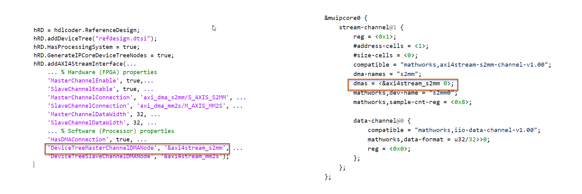
Sample Device Tree
The image shows your reference design file with the interface details. On the left is an example of a reference design file with interface details. On the right is the generated device tree file.
See Also
addDeviceTree | addDeviceTreeIncludeDirectory | addDeviceTree | addDeviceTreeIncludeDirectory | HasDMAConnection | DeviceTreeMasterChannelDMANode | DeviceTreeSlaveChannelDMANode