IP Core Reset Interface
R2026bWhen you generate an IP core for a design under test (DUT), HDL Coder™ creates internal reset‑synchronization logic that generates a global reset to reset both the DUT and the interface logic. HDL Coder generates this synchronization logic and configures it based on the model reset settings. The sources driving the global reset synchronizer depend on whether the IP core includes a register interface. When a register interface is present, HDL Coder combines the relevant reset inputs before passing them to the synchronizer. When no register interface is present, the synchronizer uses only the external IP core reset. The IP core reset interface is closely related to the IP core clock interface. For more information, see IP Core Clock Interface.
Reset Signals in IP Core With Register Interfaces
The register interface consists of logic for:
Communication with external IP by using the AXI4-Lite or AXI4 protocol
Address decoding and registers accessible through an AXI4 or AXI4-Lite interface
The AXI4 Protocol module is reset using AXI4_ARESETN, while the DUT and
IP core registers are reset by a global reset signal. This global reset combines three
sources: IPCORE_RSTN, AXI4_ARESETN, and a soft reset
triggered by writing to the Reset Register at address 0x0. These reset signals can be
synchronous or asynchronous. Asynchronous resets may cause metastability when de-asserted
during the clock latching window. To prevent this, HDL Coder automatically inserts reset
synchronization logic, shown as the Reset Sync block, which aligns the global reset signal to
the IP core clock domain.
The diagram below illustrates the clock and reset connections for the register interface and DUT, along with the DUT enable and soft reset registers.
Reset Signals in IP Core Without Register Interfaces
When your application does not require an AXI4 register interface, set the
Generate default register interface parameter to
off. For more information on how to generate an IP core without
register interface, see Generate Board-Independent HDL IP Core from Simulink Model.
In this configuration, the IP core reset signal is the sole reset source and serves as the input to the internal reset synchronizer that resets the DUT logic. This figure shows the structure of an HDL IP core generated without a register interface.
Reset Synchronization Logic
The reset signals can be either synchronous or asynchronous. Using asynchronous reset signals can result in potential metastability issues in flip-flops when the reset de-asserts in the latching window of the clock. The reset synchronization logic prevents generation of possible metastable values when combining the reset signals.
The reset synchronization logic synchronizes the global reset signal to the IP core clock
domain. When you generate an IP core, the IP core contains a Reset Sync
block that represents the reset synchronization logic. The Reset Sync block
contains two back-to-back flip-flops that are synchronous to the IPCore_CLK
signal. The flip-flops de-asserts the reset signal two clock cycles after the
IPCore_CLK signal becomes high. This synchronous de-assertion avoids
generation of a global reset signal that has possible metastable values.
Synchronous or Asynchronous Resets
The reset synchronization logic works differently depending on whether you specify the
Reset type model configuration
parameter as Synchronous or
Asynchronous on the model. This table shows the differences
between the generated HDL code for the reset synchronization logic when you generate the IP
core with synchronous and asynchronous reset signals.
If your Reset type is
Asynchronous, the synchronization logic asserts the reset signal asynchronously and de-asserts the reset signal synchronously.If your Reset type is
Synchronous, the synchronization logic asserts and de-asserts the reset signal synchronously.
Reset type is |
Reset type is |
|---|---|
...
...
reg_reset_pipe_process : PROCESS (clk, reset_in)
  BEGIN
    IF reset_in = '1' THEN
      reset_pipe <= '1';
    ELSIF clk'EVENT AND clk = '1' THEN
      IF enb = '1' THEN
        reset_pipe <= const_0;
      END IF;
    END IF;
  END PROCESS reg_reset_pipe_process;

  reg_reset_delay_process : PROCESS (clk, reset_in)
  BEGIN
    IF reset_in = '1' THEN
      reset_out <= '1';
    ELSIF clk'EVENT AND clk = '1' THEN
      IF enb = '1' THEN
        reset_out <= reset_pipe;
      END IF;
    END IF;
  END PROCESS reg_reset_delay_process;
END rtl;
|
...
...
reg_reset_pipe_process : PROCESS (clk)
  BEGIN
    IF clk'EVENT AND clk = '1' THEN
      IF reset_in = '1' THEN
        reset_pipe <= '1';
      ELSIF enb = '1' THEN
        reset_pipe <= const_0;
      END IF;
    END IF;
  END PROCESS reg_reset_pipe_process;

  reg_reset_delay_process : PROCESS (clk)
  BEGIN
    IF clk'EVENT AND clk = '1' THEN
      IF reset_in = '1' THEN
        reset_out <= '1';
      ELSIF enb = '1' THEN
        reset_out <= reset_pipe;
      END IF;
    END IF;
  END PROCESS reg_reset_delay_process;
END rtl;
|
Active-High or Active-Low Resets
HDL Coder generates different reset synchronization logic depending on whether you set
the Reset asserted
level model configuration parameter to
Active-high or Active-low. The table
shows the synchronization logic and the corresponding HDL code for both reset levels.
Reset asserted level is
|
Reset asserted level is
|
|---|---|
|
|
|
...
...
reg_reset_pipe_process : PROCESS (clk)
  BEGIN
    IF clk'EVENT AND clk = '1' THEN
      IF reset_in = '1' THEN
        reset_pipe <= '1';
      ELSIF enb = '1' THEN
        reset_pipe <= const_0;
      END IF;
    END IF;
  END PROCESS reg_reset_pipe_process;

  reg_reset_delay_process : PROCESS (clk)
  BEGIN
    IF clk'EVENT AND clk = '1' THEN
      IF reset_in = '1' THEN
        reset_out <= '1';
      ELSIF enb = '1' THEN
        reset_out <= reset_pipe;
      END IF;
    END IF;
END PROCESS reg_reset_delay_process; |
...
...
reg_reset_pipe_process : PROCESS (clk_in)
  BEGIN
    IF clk_in'EVENT AND clk_in = '1' THEN
      IF reset_in = '0' THEN
        reset_pipe <= '0';
      ELSIF enb = '1' THEN
        reset_pipe <= const_1;
      END IF;
    END IF;
  END PROCESS reg_reset_pipe_process;

  reg_reset_delay_process : PROCESS (clk_in)
  BEGIN
    IF clk_in'EVENT AND clk_in = '1' THEN
      IF reset_in = '0' THEN
        reset_out <= '0';
      ELSIF enb = '1' THEN
        reset_out <= reset_pipe;
      END IF;
    END IF;
END PROCESS reg_reset_delay_process; |
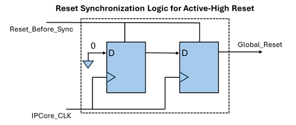
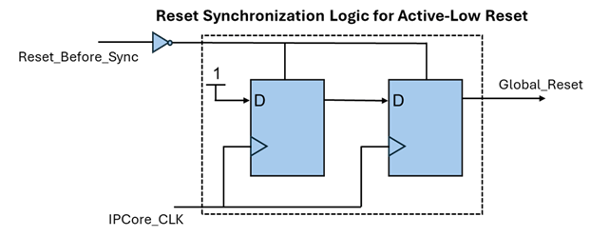
HDL Coder computes the Reset_Before_Sync signal depending on whether
you generate IP core with register interface or without register interface:
If you generate an IP core without a register interface, the
Reset_Before_Syncis the same as the IP core reset signal.If you generate an IP core with a register interface, HDL Coder determines the
Reset_Before_Syncsignal by using the IP core reset, AXI4 interconnect reset, and soft reset signals.
See Also
Reset asserted level | Reset type

