Generate Board-Independent HDL IP Core from Simulink Model
When you open the HDL Workflow Advisor and run the IP Core Generation
workflow for your Simulink® model, you can specify a generic Xilinx® platform, a generic Intel® platform, generic Microchip platform or generic platform. The workflow then generates a generic IP core
that you can integrate into any target platform of your
choice. For IP core integration, define and register a custom reference design for your
target board by using the hdlcoder.ReferenceDesign class. To learn
more, see:
Generate Board-Independent IP Core
To generate a board-independent custom IP core to use in an embedded system integration environment, such as Intel Qsys, Xilinx EDK, or Xilinx IP Integrator:
Select DUT in Simulink model and open the HDL Workflow Advisor. For example, open the model
hdlcoder_led_blinking.open_system('hdlcoder_led_blinking')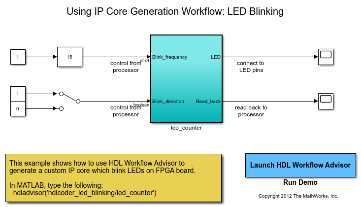
Set the path to the installed synthesis tool for the target device by using the
hdlsetuptoolpathfunction. For example, if Xilinx Vivado® is the synthesis tool, use the command:hdlsetuptoolpath('ToolName','Xilinx Vivado','ToolPath',... 'C:\Xilinx\Vivado\2024.1\bin\vivado.bat');
See HDL Language Support and Supported Third-Party Tools and Hardware for latest supported version of the synthesis tool.
Open the HDL Workflow Advisor for the DUT Subsystem. For the LED blinking model, the
led_counterSubsystem is the DUT. In the Set Target > Set Target Device and Synthesis Tool task:For Target workflow, select
IP Core Generation.For Target platform, depending on the synthesis tool and device that you are targeting, select
Generic Altera PlatformorGeneric Xilinx Platform. Click Run This Task.
In the Set Target > Set Target Interface task, select a Target Platform Interface for each port, and then click Apply. You can map each DUT port to one of these interfaces:
AXI4-Lite,AXI4,AXI4-Stream,AXI4-Stream Video,External Port, orFPGA Data Capture. For more information about these interfaces, see Target Platform Interfaces.You can also map the ports to multiple target platform interfaces. To learn more, see Generate HDL IP Core with Multiple AXI4-Stream and AXI4 Master Interfaces.
If you do not want to map the DUT ports to register interfaces, you can map them to
External Portinterfaces.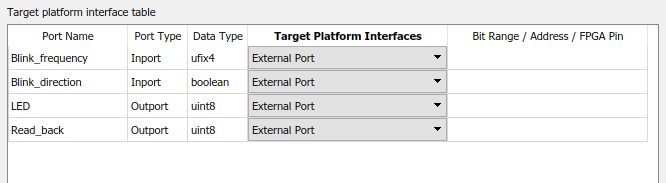
Expand the Set Code Generation Options task. Right-click the Set Optimization Options task and select Run to Selected Task.
In the HDL Code Generation > Generate RTL Code and IP Core task, you can specify:
Whether you want to connect the DUT IP core to multiple AXI Master interfaces. By default, the AXI4 Subordinate ID Width value is
12, which enables you to connect the HDL IP core to one AXI Master interface. To connect the DUT IP core to multiple AXI Master interfaces, you may want to increase the AXI4 Subordinate ID Width. When you run this task, this setting is saved on the DUT as the HDL block property AXI4SubordinateIDWidth.To learn more, see Define Multiple AXI Master Interfaces in Reference Designs to Access DUT AXI4 Subordinate Interface.
Whether you want to generate the default register interface. By default, HDL Coder™ generates register interfaces for signals such as clock, reset, ready, timestamp, and so on. If you do not want to generate any register interfaces, clear the Generate default register interface check box.
Note
If you mapped any of the DUT ports to AXI4 register interfaces in the Set Target Interface task, the code generator maps the ports to AXI4 register interfaces, whether or not the Generate default register interface check box is cleared.
Click Run This Task. When you clear the check box and run the task, the code generator saves this setting on the DUT Subsystem as the HDL block property GenerateDefaultRegisterInterface.
After running the task, HDL Coder generates the IP core files in the output folder shown the IP core folder field, including the HTML documentation. To view the IP core report, click the link in the message window.
Generate Tool-Independent IP Core
Using Generic Platform, you can generate IP core and RTL
code without setting the third-party synthesis tool. To generate IP core using
Generic Platform, follow these steps:
In step 1.1. Set Target Device and Synthesis Tool, set Target workflow to
IP Core
                            Generation
. Then, set the Target platform toGeneric Platform. Synthesis tool and target device information are not required when you set this target platform.In step 1.2. Set Target Interface, set Target Platform Interfaces for the input and output ports. You can choose
AXI4as well asexternal portas the target interface for the ports.Perform each task in the HDL Workflow Advisor until step 3.1. Set HDL Options.
In step 3.2. Generate RTL Code and IP Core, run this task to generate RTL code and IP core for your model. The generated code can be integrated on the hardware.
IP Core Without AXI4 or AXI4-Lite Register Interfaces
When you run the IP Core Generation workflow, you can also generate an HDL IP core without any register interfaces in your reference design.
To run this workflow, open the HDL Workflow Advisor, specify Generic Xilinx
Platform or Generic Altera Platform as the target
platform, and map the DUT ports to only External Port, or AXI4-Stream interface with
TLAST mapping. In addition, when you generate the HDL IP core, in the Generate
RTL Code and IP Core task, clear the Generate default register
interface check box, and then select Run This
Task.
Use this capability when:
You do not want to tune the IP core parameters by using the register interfaces.
You want to create a custom reference design without register interfaces, such as standalone FPGA boards.
In addition, avoiding generation of the register interfaces in such cases reduces hardware resource usage and design complexity.
Note
External IO and internal IO interfaces connect your HDL IP core to other
existing IPs in your custom reference design. To define these interfaces, you
use the addInternalIOInterface and
addExternalIOInterface methods
of the hdlcoder.ReferenceDesign class.
To integrate the HDL IP core, you can create a custom reference design without register interfaces. In the custom reference design, you can only use External IO, Internal IO or AXI4-Stream interface with TLAST mapping. For examples, see :
When you generate an HDL IP core without register interface such as AXI4 register interfaces, certain restrictions apply. See, IP Core Without Register Interface Restrictions .
Requirements and Limitations for IP Core Generation
Custom IP Core Generation Limitations
The DUT must be an atomic system.
The same IP core cannot use both an AXI4 interface and an AXI4-Lite interface.
The DUT cannot contain Xilinx System Generator blocks, Vitis® Model Composer blocks, or Intel DSP Builder Advanced blocks.
If your target language is VHDL®, and your synthesis tool is Xilinx ISE or Intel Quartus® Prime, the DUT cannot contain a model reference.
IP Core Without Register Interface Restrictions
You must use the
Free runningmode for Processor/FPGA synchronization.Coprocessing – blockingmode is not supported.