rotmanLens
Description
Use the rotmanLens object to create a Rotman lens in microstrip
form.
A Rotman lens is a passive phase-shifting network used with antenna arrays in beam forming and steering applications.
The structure of a Rotman lens consists of several regions as shown below.
Rotman Lens Regions
Input Beam Ports - The input beam ports lie on a semi-circular arc along the perimeter of the parallel plate region and provide connectivity between the RF excitation source (typically a single radio transmitter and/or radio receiver). The array scan angle is controlled by selecting which beam port is connected to the excitation source. The number of beam ports determines the incremental change in the scan angle of the antenna array.
Parallel Plate Region - The parallel plate region provides the phase delays between the input beam ports and output ports of the lens. It consists of the lens and ground plane conductive layers and the dielectric substrate sandwiched between the conductive layers.
Output Ports – The output ports lie in a curved arc along the perimeter of the parallel plate Region exactly opposite the input beam ports. The output ports are connected to the delay lines region of the lens. Each output port connects to an individual delay line.
Delay Lines – The Delay Lines provide time delays and connectivity between the Output Ports and the Linear Array regions of the lens.
Linear Array - The linear array region lies along a straight line and provides connectivity from the delay lines to the antennas.
Dummy Ports - The dummy ports lie symmetrically along the two side walls of the lens. They are terminated with matching impedances to prevent reflections from occurring along the side walls of the lens.
The design of the Rotman lens is determined by its geometrical configuration as shown below.
Rotman Lens Geometry
C is the semi-circular arc of the beam inputs.
S1 is the arc of the beam output.
S2 is the line of the linear array
F0 is the on-axis focal point of the lens located at the center of arc C.
F1 and F2 are the off-axis foci points of the lens located equidistant from F0 on arc C.
d is the Array Port spacing along S2.
w0 is the on-axis delay line electrical delay.
w are the off-axis delay lines electrical delays.
α is the beam port angle.
ψ is the maximum scan angle of the array.
Creation
Description
lens = rotmanLens creates a Rotman lens object with default
properties.
lens = rotmanLens( sets Properties using one or more
name-value arguments. For example, Name=Value)lens = rotmanLens(NumBeamPorts=4)
creates a Rotman lens with four beam ports. Properties not specified retain their
default values.
Properties
Object Functions
current | Calculate and plot current distribution |
dgs | Create defected ground structure of PCB element |
feedCurrent | Calculate current at feed port |
mesh | Change and view mesh properties of metal or dielectric in PCB component |
show | Display PCB component structure or PCB shape |
layout | Plot all metal layers and board shape |
charge | Calculate and plot charge distribution |
shapes | Extract all metal layer shapes of PCB component |
sparameters | Calculate S-parameters for RF PCB objects |
Examples
Create and visualize a Rotman Lens in microstrip form.
Create Lens
Create a Rotman Lens.
lens = rotmanLens
lens =
  rotmanLens with properties:

          NumBeamPorts: 6
             BeamTaper: [1×1 traceTapered]
         BeamPortAngle: 30
         NumDummyPorts: 2
         NumArrayPorts: 6
            ArrayTaper: [1×1 traceTapered]
      ArrayPortSpacing: 0.0167
          MaxScanAngle: 20
     OnaxisFocalLength: 0.1099
    OffaxisFocalLength: 0.0962
                Height: 5.0800e-04
             Substrate: [1×1 dielectric]
             Conductor: [1×1 metal]
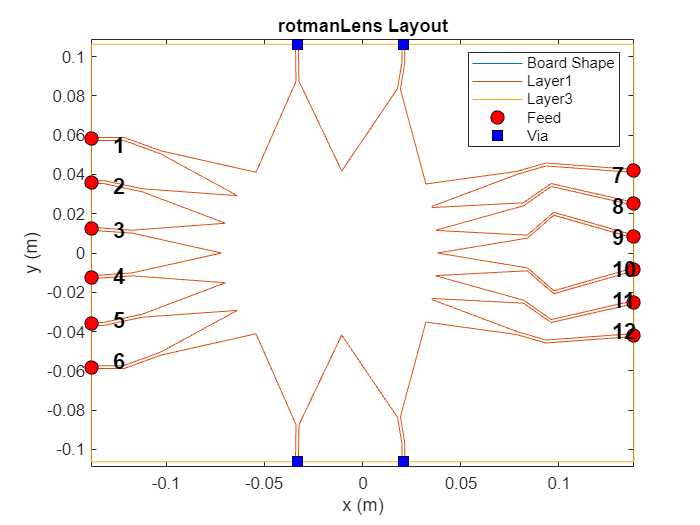
Visualize the Lens
Use the show and layout functions to visualize the PCB and port numbers.
show(lens)
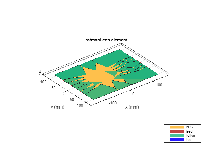
layout(lens)
Create and visualize a Rotman lens with user defined properties.
Create Lens
Create a Rotman lens with these properties: 4 beam ports, 4 array ports, 4 dummy ports, 40 degree beam port angle, 30 degree maximum scan angle, and copper conducting layer.
lens = rotmanLens(NumBeamPorts=4,NumArrayPorts=4,NumDummyPorts=4,BeamPortAngle=40,MaxScanAngle=30,Conductor=metal('copper'))lens =
rotmanLens with properties:
NumBeamPorts: 4
BeamTaper: [1×1 traceTapered]
BeamPortAngle: 40
NumDummyPorts: 4
NumArrayPorts: 4
ArrayTaper: [1×1 traceTapered]
ArrayPortSpacing: 0.0167
MaxScanAngle: 30
OnaxisFocalLength: 0.1099
OffaxisFocalLength: 0.0962
Height: 5.0800e-04
Substrate: [1×1 dielectric]
Conductor: [1×1 metal]
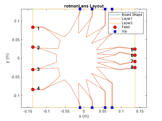
Visualize Lens
Use the show and layout functions to visualize the PCB and port configuration.
show(lens)
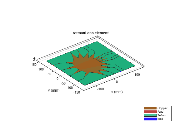
layout(lens)
References
[1] Hansen, R.C. Design Trades for Rotman Lenses IEEE Transaction on Antennas and Propagation, Vol. 39, No. 4, April 1991
Version History
Introduced in R2024b