Main Content

SIWLine

Create an SIW line in microstrip form

Since R2023b

    Description

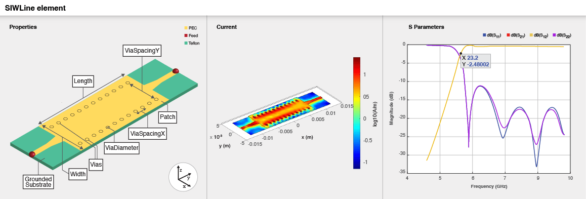
    Use the SIWLine object to create a Substrate Integrated Waveguide (SIW) transmission line in microstrip form.

    Three part image from right to left: Default image of a SIW transmission line. Current distribution on the transmission line. S-parameters plot of the SIW transmission line.

    Creation

    Description

    example

    line = SIWLine creates a default SIW line. Default substrate is Teflon with a thickness of 0.254e-3 m.

    example

    line = SIWLine(Name=Value) sets Properties using one or more name-value arguments. For example, SIWLine(Width=0.008) creates a line with width 0.008 m. Properties not specified retain their default values.

    Properties

    expand all

    Feed line shape is specified as FeedLine .

    Example: line.FeedLine = traceRectangular

    Data Types: obj.shape

    Length is specified as a positive scalar

    Example: Line = SIWLine(Length = 0.02161)

    Data Types: double

    Width is specified as a positive scalar

    Example: Line = SIWLine(Width = 0.0077)

    Data Types: double

    Via spacing is specified as a two element positive vector. X-spacing is the center-to-center spacing between adjacent vias in the X direction. Y-spacing is the center-to-center spacing between adjacent vias in the Y direction.

    Example: Line = SIWLine(ViaSpacing = [1.3e-3 5.1e-3])

    Data Types: double

    Via diameter is specified as a positive scalar.

    Example: Line = SIWLine(ViaDiamater = 0.49e-3)

    Data Types: double

    Height is specified as a positive scalar.

    Example: Line = SIWLine(Height = 0.248)

    Data Types: double

    Ground plane width is specified as a positive scalar.

    Example: Line = SIWLine(GroundPlaneWidth = 0.008)

    Data Types: double

    Conductor is specified as a metal object.

    Example: line.Conductor = metal('Copper')

    Data Types: string

    Substrate is specified as a dielectric object.

    Example: line.Substrate = dielectric('FR4')

    Data Types: string

    Flag to add a metal shielding to the PCB component, specified as a logical 0 or logical 1. The default value is logical 0.

    Example: IsShielded = true or 1 add a metal shield.

    Note

    To enable FEM solver required for the metal shield property, download the Integro-Differential Modeling Framework for MATLAB. To download this add-on:

    1. In the Home tab Environment section, click on Add-Ons. This opens the add-on explorer. You need an active internet connection to download the add-on.

    2. Search for Integro-Differential Modeling Framework for MATLAB and click Install.

    3. To verify if the download is successful, run

      matlab.addons.installedAddons
      in your MATLAB® session command line.

    4. On Windows, to run the IDMF add-on, you must install the Windows Subsystem for Linux (WSL). To install WSL, see Install Linux on Windows with WSL.

      The Windows Defender Firewall can block the PostgreSQL server when using the IDMF add-on. To resolve this issue, you can allow the server to communicate on desired networks if the firewall prompts. Alternatively, you can manually add the executable file of the PostgreSQL server located in <matlabroot>\sys\postgresql\win64\PostgreSQL\bin\postgres.exe. For more information regarding firewalls, see Allowing apps through Windows Defender Firewall .

    Data Types: logical

    This property is read-only.

    Metal shield for the PCB component, specified as a shape.Box object. The length and width of the box must be equal to the length and width of the ground plane. The center of the box is at [0 0 Shielding.Height]. You can modify the property after creating the object.

    Dependencies

    To enable the Shielding property, set the IsShielded property to true or 1.

    Type of RF connector assembled at the feed locations of the PCB component, specified as a RFConnector object.

    Example: Create connector from RFConnector object like this: coaxial = RFConnector adds a coaxial connector.

    Dependencies

    To enable the Connector property, set the IsShielded property to true or 1.

    Object Functions

    chargeCalculate and plot charge distribution
    currentCalculate and plot current distribution
    dgsCreate defected ground structure of PCB element
    feedCurrentCalculate current at feed port
    layoutPlot all metal layers and board shape
    meshChange and view mesh properties of metal or dielectric in PCB component
    shapesExtract all metal layer shapes of PCB component
    showDisplay PCB component structure or PCB shape
    sparametersCalculate S-parameters for RF PCB objects
    RFConnectorCreate RF connector

    Examples

    collapse all

    Create and visualize default SIW transmission line

    line = SIWLine
    line = 
      SIWLine with properties:
    
                FeedLine: [1x1 traceTapered]
                  Length: 0.0153
                   Width: 0.0074
              ViaSpacing: [0.0012 0.0050]
             ViaDiameter: 5.1000e-04
                  Height: 2.5400e-04
        GroundPlaneWidth: 0.0074
               Substrate: [1x1 dielectric]
               Conductor: [1x1 metal]
              IsShielded: 0
    
    
    show(line)

    Create and visualize SIW transmission line with rectangular feed line

    line = SIWLine;
    line.FeedLine = traceRectangular("Length",3e-3,"Width",2e-3)
    line = 
      SIWLine with properties:
    
                FeedLine: [1x1 traceRectangular]
                  Length: 0.0153
                   Width: 0.0074
              ViaSpacing: [0.0012 0.0050]
             ViaDiameter: 5.1000e-04
                  Height: 2.5400e-04
        GroundPlaneWidth: 0.0074
               Substrate: [1x1 dielectric]
               Conductor: [1x1 metal]
              IsShielded: 0
    
    
    show(line)

    Version History

    Introduced in R2023b