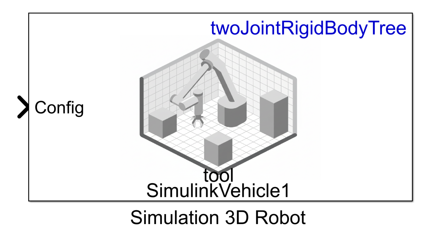
Simulation 3D Robot
Libraries:
Robotics System Toolbox /
Simulation 3D
Description
Note
Simulating models with the Simulation 3D Robot block requires Simulink® 3D Animation™.
The Simulation 3D Robot implements a robot in a 3D simulation environment using Unreal Engine®.
To use this block, ensure that the Simulation 3D Scene
Configuration block is in your model. If you set the Sample
time parameter of the Simulation 3D Robot block to
-1, the block inherits the sample time specified in the Simulation
3D Scene Configuration block.
Examples
This example shows simulation of an automated assembly to demonstrate virtual commissioning applications. The assembly line is based on a modular industrial framework created by ITQ GmbH known as Smart4i. This system consists of four components: two robotic workcells that are connected by a shuttle track and a conveyor belt. One of the two robots places cups onto the shuttle, while the other robot places balls in the cups. A slider then delivers those cups to a container. This simulation uses Stateflow® to control the system control and demonstrates how you can use Unreal Engine® to simulate a complete virtual commissioning application in Simulink®. For an example showing how to deploy the main logic in Stateflow using Simulink PLC Coder™, see Generate Structured Text Code for Shuttle and Robot Control (Simulink PLC Coder).
System Overview
The core environment has five components that form the assembly line:
Robot 1 (Comau) — The first robot is a Comau Racer V3. This robot picks up the cups with a suction gripper and puts them in the shuttles.
Robot 2 (Mitsubishi) — The second robot is a Mitsubishi RV-4F. The camera sensor in the workcell of this robot detects the balls and then this robot picks up the balls with a suction gripper, and places each of them in a separate cup.
Shuttle Track & Shuttles — The shuttle track moves four shuttles to the Robot 1, then to the Robot 2, and then to the slider before returning to the Robot 1.
Slider — The conveyor belt carries the cups away from the track and into a container.
Static Machine Frame — The remaining non-moving model parts comprise of the static machine frame, which serves as the base for the assembly. It includes the two work cells housing the robots, as well as the base for the center assembly.

This system is created using CAD data provided by ITQ GmbH. MATLAB® has the imported CAD files, which are preprocessed using Simulink 3D Animation™ functions and then saved to a MAT file for reuse.
During normal execution, Robot 1 picks up cups from a tray in the Robot 1 workcell and places them in an empty shuttle that is waiting for the cup. Placing the cup in the shuttle triggers the filled shuttle to move along the shuttle track to reach Robot 2 and create an instance of the ball in the Robot 2 workcell. The location of this ball in Robot 2 workcell is random. A camera positioned above the area where the ball appears in the Robot 2 workcell captures the image of the ball and communicates it to the Deep Learning network. The network uses this information to detect the position of the ball for Robot 2 to pick it up. Once the shuttle containing the cup stops at Robot 2 workcell, Robot 2 picks up the ball and places it inside the cup. Then the shuttle moves to the unloading station, where it releases the cup onto the slider. The cup then slides into a container placed at the end of the slider. After releasing the cup onto the slider, the shuttle moves back to the Robot 1 workcell and waits to receive another cup.
This example makes use of variant subsystems to provide modularity. One such variant is used for sensing, and has two settings:

ManualDetection
—This default variant requires a minimal set of products to run. No camera is used; instead, the ball is placed at the same location each time and that location is hard-coded in the model.CameraBasedDetection
—This variant additionally uses camera feedback to detect the ball, as described above, more closely mirroring the behavior of the original ITQ system. However, this variant additionally requires Deep Learning Toolbox™, Image Processing Toolbox™, and Computer Vision Toolbox™ to run.
Model Overview
This example uses the assembly line CAD data, robot model files and shuttle trajectory data. Download and unzip these data files.
downloadFolder = matlab.internal.examples.downloadSupportFile ...
    ("R2023a/sl3d/examples/","smart4i_data.zip");
unzip(downloadFolder);
Open the model to view the block diagram:
smart4iModel = "smart4i_model.slx";
open_system(smart4iModel);
Version = "Simulation3DRobot"
SensorVersion =
"ManualDetection"

The model has four main parts, which are detailed below:
Scene Creation & Configuration
System Control Logic
Ball Detection
Actor Motion Control
Scene Creation & Configuration
This section has two main functions.
Simulink 3D Scene Configuration block, that defines the baseline Unreal Engine environment which the model connects to.
Actor block named Prepare World, that is used to set up the environment defined in the previous section. To do this, the actor calls the setup script,
smart4i_setupworld.m, which loads and configures the scene.
In this example, the scene was prepared using these tools:
Simulink 3D Animation tools import the workcells, shuttles, and a static machine frame from CAD files into MATLAB.
The
load(Simulink 3D Animation) function of thesim3d.Actor(Simulink 3D Animation) object to import the two robots by loading from their URDF files.The
sim3d.Actor(Simulink 3D Animation) andsim3d.World(Simulink 3D Animation) objects to create the slider.

System Control Logic
The Stateflow chart in the System Control Logic section determines the main system behavior.
Inside the Stateflow chart, there are three main sections, listed from bottom to top:
Shuttle Control Logic — These charts in this section control the motion of each of the four shuttles. The charts output three-dimensional vectors containing the specified shuttle XY-position, and the rotation about the Z-axis.
Robot Control Logic — The charts in this section control the motion of the two robot manipulators. The charts output three-dimensional vectors containing the suction gripper translations. These charts also dictate the actions for the cup and ball: the chart for Robot 1 indicates when cups should be attached or detached, and the chart for Robot 2 controls creation of new ball instances so that the balls can be picked up, as well as instruction to pick them up.
Cup Instance Logic — This chart controls the destruction of old cups after the slider drops the cups into the container.


The overall Stateflow chart has a number of outputs:
The chart uses an index to indicate when a new ball instance should be created.
Four shuttle outputs are used to define the pose of the shuttles.
There are four outputs for robot control: f_reset_r1 and pos_r1, and f_reset_r2 and pos_r2, for robots 1 and 2, respectively. Whenever robot motion is needed, the f_reset flags are switched from 0 to 1 to trigger a trajectory subsystem. The trajectory generation subsystem then generates a new task-space trajectory between the robot's current pose and the new desired target position, and passes that to the actor control subsystem, which translates the task-space trajectories to joint-space motion and defines robot physics. This subsection is discussed in greater detail in the Actor Control section below.
Five outputs, led by the cup's actor ID, ID1_out, govern the motion and expected actions of the cup. These are passed directly to actor control blocks for the cup physics.
Five outputs, starting with the ball's actor ID, ID2_out, define the pose and expected actions of the ball. These are passed to the Ball Detection subsystem, which finds the ball using either a manual lookup of the actor ID, or a camera-based detection, depending on the selected variant. This output is fed back into the Stateflow chart for use on the next step. The ball outputs are also passed to actor control blocks for the ball physics.
The final three outputs govern cup creation and destruction. These commands are passed to actor control blocks that execute the instructions.
While all the system logic is in the Stateflow chart, the actual control of all actors -- the two robots, the shuttles, cups, and balls -- happens outside the chart in the Actor Motion Control section.
Ball Detection
The Ball Detection subsystem identifies the location of the ball to be placed. When the sensor variant is set to manual mode, this value is read by simply querying the ID of the ball actor and reading the pose. However, when the variant is set to Camera-based detection, a Simulation 3D Camera Get block is used to view the ball and identify its position.

The ball position in the Robot 2 workcell is the same but with a small random offset to reflect the real-life variability caused by the ball rolling. The findBallLoc triggered subsystem takes the image data from the camera to detect the ball.

In this subsystem, the Deep Learning Object Detector block from the Deep Learning Toolbox™ takes the image data and outputs the bounding boxes. The bounding boxes provide information about the size and location of the ball in the image. The findBallXY MATLAB function converts the bounding boxes to the *XY-*positions of the ball and then returns those positions to the Stateflow chart for Robot 2.
The Deep Learning Object Detector was pretrained in MATLAB by creating a video of the ball at random locations and using the Video Labeler app from the Computer Vision Toolbox to create a labeled dataset and train a yolov2ObjectDetector object.
Actor Control
To move the objects in the scene, the system translates motion commands to the desired behavior. The Actor Control section defines the motion of the two robots, the shuttles, and the existence and initial position of the ball. There are two methods for settings robot poses, which can be switched with radio button as mentioned in the Select Variant. 
The robot simulation in the Simulink 3D can be performed with Simulation 3D Actor block as well as with Simulation 3D Robot block. The respective block connections are activated based on variant selection from radio button. Once variant is selected, you can update model to see activated connection.
Use a Simulation 3D Robot Block
The Simulink 3D Robot block is designed for position robotic actors. It offers improved performance over a set of transform blocks and allows the user control of proximity-based grasp and release actions. The Robot 1 and Robot 2 subsystem performs robot motion as well as grasp-release target in the Simulink 3D world.

Use a Simulink 3D Actor Block Together with Get Transform Blocks
This mechanism of control allows more complete control, enabling the user to freely position any of the robot bodies regardless of kinematic constraints. However, the complete subsystem requires additional blocks to complete the same joint position task, resulting in a subsystem that is less performant than the Simulink 3D Robot block. Each robot body corresponds to an actor in the Unreal Engine environment. Robot 1 and Robot 2 subsystems control the motion of Robot 1 and Robot 2 respectively, to position the robot actors such that the robots reach the specified poses. This diagram shows the contents of each subsystem:

These steps rely on kinematic computations on the robot which requires a kinematic model of the robot in MATLAB using the rigidBodyTree object. During scene creation, which happens in a model callback, the system imports the rigid body trees for Robot 1 and Robot 2 from their original URDF files to the base MATLAB workspace. Additionally, in the same callback, joint limits derived from the specifications for each robot are applied. This ensures that the robot's feasible joint positions will be incorporated during the inverse kinematics phase of trajectory generation.
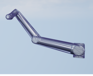
show(Robot1);
title("Robot 1 (Comau Racer V3)");
Inspect each robot to see the bodies it contains. These bodies correspond to the actors in the scene. In the Unreal Engine scene, each actor pose is defined relative to the parent body.
showdetails(Robot1)
--------------------
Robot: (6 bodies)

 Idx     Body Name     Joint Name     Joint Type     Parent Name(Idx)   Children Name(s)
 ---     ---------     ----------     ----------     ----------------   ----------------
   1        part_1        joint_1       revolute         base_link(0)   part_2(2)
   2        part_2        joint_2       revolute            part_1(1)   part_3(3)
   3        part_3        joint_3       revolute            part_2(2)   part_4(4)
   4        part_4        joint_4       revolute            part_3(3)   part_5(5)
   5        part_5        joint_5       revolute            part_4(4)   tool(6)
   6          tool        joint_6       revolute            part_5(5)
--------------------
Given the robot models, it is possible to translate a suction gripper pose to actor motion in two mains steps, as specified by the two areas in the model:
Compute Robot Configuration from Target Pose — The Simulink model combines the input translation and the desired orientation into one signal and inputs that signal as a pose to the Inverse Kinematics block. This block converts the desired suction gripper pose to a set of joint angles, known as the joint configuration.
Specify the Hierarchical Actor Poses — Since each robot body pose is specified relative to a parent robot body, you must convert the set of joint angles into six relative poses that relate each body to their corresponding parent body. The model uses six Get Transform blocks to find the relative poses between two specified bodies.
Note that the suction gripper does not act on the cup or ball in any way. Instead, cups and balls are picked by reparenting them to the suction gripper, effectively adding the picked part to the robot hierarchy. The supervisory logic in the Stateflow chart sets the events that trigger the Simulink functions calling the attach and detach functions.
Ball Instance
When the Stateflow chart triggers the system to create a new ball, the Simulation 3D Actor block named Ball Instance commands the creation of a new ball for Robot 2 to pick up. The block adds a random offset to the position of the ball to simulate real-world conditions caused by the ball rolling, but the detection subsystem ensures that the control logic gets the exact ball position.
Shuttles
The translation and orientation of the shuttle is set in space to make it move around the track. The Stateflow chart outputs XY-position and orientation about the Z-axis to the Shuttles subsystem to set the poses of the appropriate actors in the Unreal Engine world.
Simulate the Model
Open the model and click Run to start the simulation.
open_system(smart4iModel);
The simulation takes around 30-45 seconds to start in 3D viewer owing to a large number of actors in the scene.

Simulate joint-space trajectories for a rigid body tree robot model and visualize the results with Simulation 3D Robot block in the Simulink 3D world.
Model Overview
Load the model with the following command:
open_system("SL3DJointSpaceManipulatorTrajectory")This example uses a Kinova Gen3 manipulator, which is stored in the model workspace. However, load and visualize the robot with the following commands:
gen3 = loadrobot("kinovaGen3","DataFormat","column");
The model is split into two sections:
Manipulator Trajectory Tracking
Visualization in Simulink 3D™
Manipulator Trajectory Tracking
The Polynomial Trajectory block generates continuous joint-space trajectories from random sets of waypoints in the range [-0.375*pi 0.375*pi], stopping at each of the waypoints. The Joint-Space Motion Model block simulates the closed-loop tracking of these trajectories for a Kinova Gen3 manipulator with computed-torque control.

Visualization with Simulation 3D Robot block in Simulink 3D™
The Simulation 3D Robot block inserts the manipulator into the Simulink 3D world defined by the RigidBodyTree object input. The Get Transform block is used to get the position of the end effector, which is then converted from a homogeoneous transform matrix to a translation vector.

Simulate the Model
In the model, pacing is active, as indicated by the clock symbol below the run button:

This ensures that the model is slowed down to near real-time speed, so that the visualization can be updated at a realistic pace.
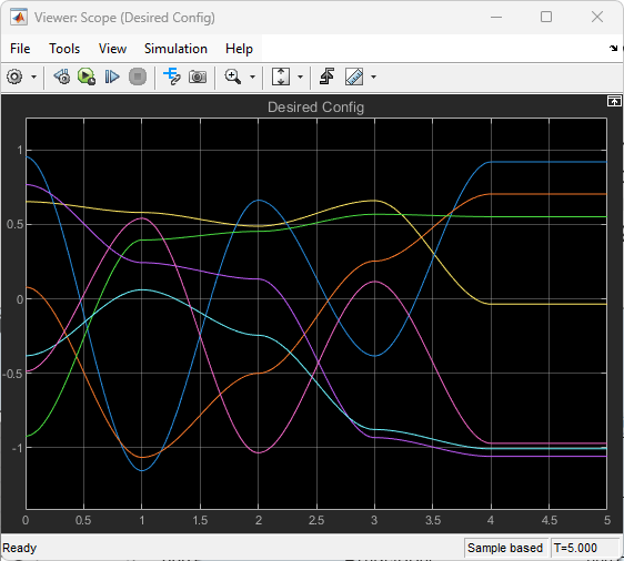
Trajectory Visualization
By default, the model opens the scopes that display velocity and position information. However, if they are closed, the scopes can be opened by double-clicking the associated viewer icons:

Visualize robot motion in Simulink 3D world.
The scopes show the tracking results of the Joint Space Motion Model block. As can be seen on the left in the figures below, the initial configuration of the robot differs from the reference trajectories, but the controlled motion ensures that the trajectory is reached and tracked for the duration of the simulation. The final scope displays the X, Y, and Z position of the end effector in the world frame.


Ports
Note
This block processes all the input and output values using the right-hand rule world coordinate system. For more information, see Coordinate Systems for Unreal Engine Simulation in Robotics System Toolbox.
Input
Output
Parameters
To edit block parameters interactively, use the Property Inspector. From the Simulink Toolstrip, on the Simulation tab, in the Prepare gallery, select Property Inspector.
Parameters
Robot model source, specified as either RigidBodyTree
Object or Robot Library:
RigidBodyTree Object— Specify arigidBodyTreeobject from the MATLAB® workspace.Robot Library— Select a robot rigid body tree model from the Robotics System Toolbox™ Robot Library Data. For more information, see Robotics System Toolbox Robot Library Data.
Robot rigid body tree model, specified as a rigidBodyTree object or the name of a rigid body tree model in the
Robotics System Toolbox Robot Library Data depending on the value of the Input type parameter:
RigidBodyTree Object— Specify arigidBodyTreeobject from the MATLAB workspace.Robot Library— Select a robot rigid body tree model from the Robotics System Toolbox Robot Library Data. For more information, see Robotics System Toolbox Robot Library Data.
Name of actor to represent the robot in Unreal Engine scene, specified as a string scalar.
Select this parameter to use an existing actor in the Unreal Engine scene to represent the robot. When you select this parameter, the Simulation 3D Robot uses the actor in the scene with the name specified by the Actor name parameter. If this parameter is cleared, the Simulation 3D Robot creates a new actor with the specified actor name in the scene to represent the robot.
Sample time of the block, in seconds, specified as a positive scalar. The 3D simulation environment frame rate is the inverse of the sample time.
If you set the sample time to -1, the block inherits its sample time from
the Simulation 3D Scene Configuration block.
Initial Values
Initial translation of the robot base, specified as a three-element row vector, in the form [x, y , z]. x, y , and z are the translations along the x, y, and z axes respectively. Units are in meters.
Initial rotation of the robot base, specified as a three-element row vector, in the form [yaw, pitch, roll]. yaw, pitch, and roll are the rotations about the z, y, and x axes respectively. Units are in radians.
Initial joint configuration, specified as an N-element vector. N is equal to the number of movable joints in the rigid body tree.
Grasp Settings
Use the Select body button to select an end-effector body name from one of the rigid bodies in the robot rigid body tree.
Dependencies
To enable this parameter, select the Enable grasp settings input signals parameter.
Select this parameter to enable input of translation and rotation difference between the end effector and the target actor at the TargetEETranslation and TargetEERotation input ports, respectively.
Clear this parameter to specify the translation and rotation difference using the End effector to target translation and End effector to target actor rotation parameters.
Dependencies
To enable this parameter, select the Enable grasp settings input signals parameter.
Translation difference between the end effector and the target actor to grasp, specified as a three-element row vector, in the form [x, y , z]. x, y , and z are the translations along the x, y, and z axes respectively. Units are in meters.
Dependencies
To enable this parameter, select the Enable grasp settings input signals parameter.
Rotation difference between the end effector and the target actor to grasp, specified as a three-element row vector, in the form [yaw, pitch, roll]. yaw, pitch, and roll are the rotations about the z, y, and x axes respectively. Units are in radians.
Dependencies
To enable this parameter, select the Enable grasp settings input signals parameter.
Select this parameter to automatically grasp target actors using the end effector when target actors are within specified region of the end effector.
Dependencies
To enable this parameter, select the Enable grasp settings input signals parameter.
Select this parameter to enable input of grasp regions at the GraspRegionTranslation and GraspRegionRotation input ports.
Clear this parameter to specify the grasp regions using the End effector to target actor grasp region translation difference and End effector to target actor grasp region rotation difference parameters.
Dependencies
To enable this parameter, select the Enable region-based target actor grasp approach parameter.
Translation difference of grasp region, specified as a three-element row vector, in the form [x, y , z]. x, y , and z are the translations along the x, y, and z axes respectively. Units are in meters.
Dependencies
To enable this parameter, select the Enable region-based target actor grasp approach parameter.
Rotation difference of grasp region, specified as a three-element row vector, in the form [yaw, pitch , roll]. yaw, pitch, and roll are the rotations about the z, y, and x axes respectively. Units are in radians.
Dependencies
To enable this parameter, select the Enable region-based target actor grasp approach parameter.
rigidBodyTree Geometry Settings
Set the parameters in this tab to enable the visualization of the rigid body tree geometry in the 3D visualization environment.
Visual Geometry Visualization
Select this parameter to add rigid body tree visual geometry in the 3D visualization environment.
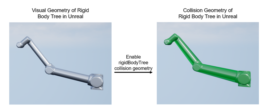
Collision Geometry Visualization
Select this parameter to visualize rigid body tree collision geometry in the 3D visualization environment.
Color of the rigid body tree collision geometry being visualized in the 3D visualization environment, specified as a three-element row vector.
Transparency of the rigid body tree collision geometry being visualized in the 3D visualization environment, specified as a scalar.
This image shows the Unreal Engine collision geometry generated internally for physics simulation.
Enabling rigid body tree collision visualization from the block overlays Robotics System Toolbox collision geometry in the Unreal Engine scene for visualization only and does not modify or replace Unreal Engine collision used for physics simulation. This image shows the Robotics System Toolbox visual geometry in the Unreal Engine scene and the Robotics System Toolbox collision geometry visualized in the same scene.
Inputs
Select this parameter to specify desired robot configurations at the Config input port.
Dependencies
To enable this parameter, clear the Enable grasp settings input signals parameter.
Select this parameter to enable the Grasp Settings tab to control how the robot grasps target actors, and the TargetActor and ActivateTargetGrasp input ports.
Select this parameter to specify the translation and rotation of the robot base at the Translation and Rotation ports, respectively. Enable this port for rigid body tree models of mobile robots and mobile manipulator robots.
Outputs
Select this parameter to output the ground truth configuration at the GroundTruthConfig output port.
Select this parameter to output the grasping status of the end effector at the IsTargetGrasped output port.
Select this parameter to output ground truth pose of robot base at the GroundTruthTranslation and GroundTruthRotation output ports.
Version History
Introduced in R2024a