Measure Jitter in Simulink Using Jitter Measurement Block
This example shows how to use the Jitter Measurement block to measure timing error and estimate jitter components in a Simulink model of a SerDes system. For a more detailed look at individual metrics, see Model and Measure Jitter in SerDes System.
The Jitter Measurement block provides the metrics from the jitter function in a fixed-memory-footprint package for use in Simulink. If memory capacity is a limiting factor, or if a Simulink block is preferable, use the Jitter Measurement block. If you want automatic amplitude axis scaling, or if a MATLAB function is preferable, use jitter.
Create Model
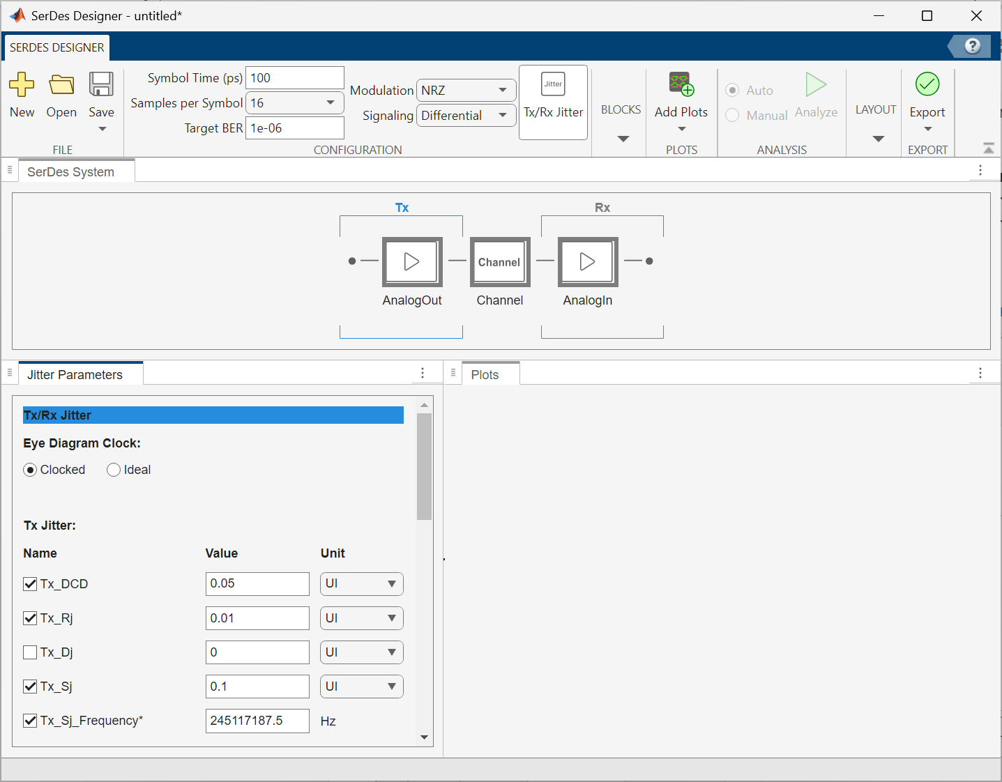
Open the SerDes Designer app.
serdesDesigner
Open the Jitter Parameters panel by clicking the Tx/Rx Jitter button in the toolstrip. Check the boxes next to Tx_DCD, Tx_Rj, Tx_Sj, and Tx_Sj_Frequency. Leave Tx_Dj unchecked. Set the Value for the Tx jitter parameters as follows:
Tx_DCD (half the Pk-Pk DCD) = 5 ps =
0.05 UITx_Rj (RMS RJ) = 1 ps =
0.01 UITx_Sj (SJ Amplitude) = 10 ps =
0.1 UITx_Sj_Frequency (SJ Frequency) =
245.1171875 MHz=245117187.5 Hz
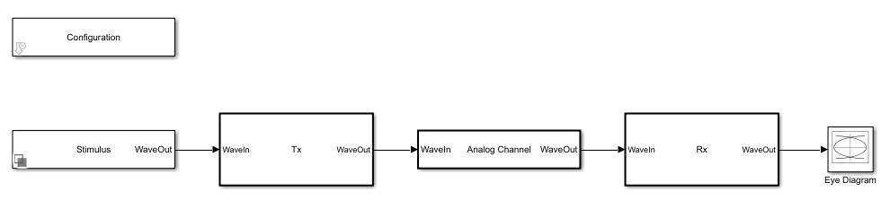
Export the system to Simulink.
If you need to modify the jitter parameters from the Simulink model, use the SerDes IBIS-AMI Manager found in the Configuraiton block. The TX jitter parameters can be found in the AMI - Tx tab of the SerDes IBIS-AMI Manager. AMI parameters' values can be modified by modifying the Current value field.
Add a Jitter Measurement block from the SerDes Toolbox Utilities library to the model. Connect the Jitter Measurement block's wave input port to the output of the Rx subsystem.
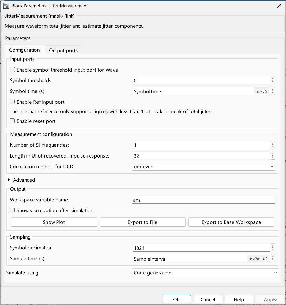
Double-click on the Jitter Measurement block to open its dialog. In the Configuration tab, set the following parameters:
Symbol thresholds:
0Symbol time (s):
SymbolTimeLength in UI of recovered impulse response:
32Symbol decimation:
1024Sample time (s):
SampleInterval
SymbolThresholds tells the jitter measurement the amplitude(s) at which to detect threshold crossings, and the modulation of the signal under test because the number of threshold values depends on the modulation (PAM2/NRZ = 1, PAM3 = 2, ...). Reducing Length in UI of recovered impulse response from its default value of 256 to 32 applies the assumption that UI 33+ of the recovered response are zero. This reduces the impact of non-ISI jitter on the impulse response, and subsequently on the recovered ISI estimate. Symbol decimation sets the number of symbols between metric value calculations. This parameter balances between accuracy and precision of the metrics versus frequency of updates to their values.
In the Output ports tab, enable ports for the following metrics by checking their boxes:
TJrms - RMS Total Jitter
RJrms - RMS Random Jitter
SJ - Sinusoidal Jitter
DCDpkpk - Peak-to-Peak Jitter correlated with duty cycle distortion
ISIrms - RMS Jitter correlated with intersymbol interference
Apply the changes.
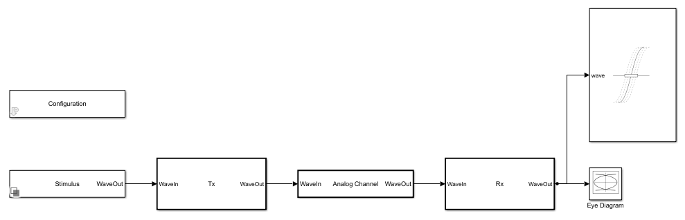
Add a Scope block and two Terminator blocks to the model. The frequency and phase of the sinusoidal jitter estimate are on a different scale from the RMS (Root-Mean-Square) and PKPK (Peak-to-Peak) metric values. Connect the SJf and SJp output ports of the Jitter Measurement block to the Terminator blocks. Connect the rest of the outputs of the Jitter Measurement block (including SJa, the amplitude of the sinusoidal jitter estimate) to the scope.
The model EndToEndJitterModel included with this example has been pre-configured as described above, for your convenience.
model = "EndToEndJitterModel";
open_system(model);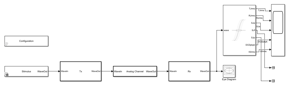
Simulate and View Results
Run the simulation.
out = sim(model);

Note: If you do not provide the values for SymbolThresholds, ReferenceThresholds, SampleInterval, or SymbolTime, the function heuristically calculates these values.
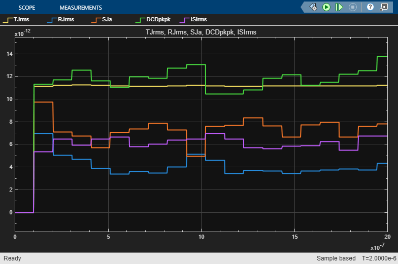
The Scope block shows the evolution of the various jitter metrics' values as the simulation progresses. Additionally, the variable ans in the base workspace holds metric results from calling jitter on the last full frame of data. Change the name of this variable by changing the Workspace variable name parameter of the Jitter Measurement block.
disp(jitterStructToEngineeringUnits(ans));
               Value     Unit
               ______    _____

    TJrms      11.784    "ps"
    TJpkpk     55.931    "ps"
    RJrms      4.5578    "ps"
    DJrms      13.017    "ps"
    DJpkpk     61.695    "ps"
    SJa        9.8606    "ps"
    SJf        244.14    "MHz"
    SJp        -1.365    "rad"
    DDJrms     10.798    "ps"
    DDJpkpk    47.444    "ps"
    DCDrms     6.8746    "ps"
    DCDpkpk    13.739    "ps"
    ISIrms     7.4005    "ps"
    ISIpkpk    36.142    "ps"
For a more detailed discussion of individual metrics, see Model and Measure Jitter (LINK TODO).
Measure ISI Separately
The estimation of jitter due to intersymbol interference relies on reconstruction of an impulse response from the measured data. This process works best in an environment without jitter other than ISI and requires a random or pseudorandom symbol pattern. For more details, see Model and Measure Jitter (LINK TODO).
Use the impulse response that the Channel block stored in the model workspace to characterize ISI in the system.
bdclose(model);
load_system(model);
modelWorkspace = get_param(model,"ModelWorkspace");
impulseResponse = getVariable(modelWorkspace,"ChannelImpulse");
n = getVariable(modelWorkspace,"RowSize");
sampleInterval = getVariable(modelWorkspace,"SampleInterval");
impulseResponse = impulseResponse.Value(1:n.Value).*sampleInterval.Value;
Open the dialog of the Jitter Measurement block and expand the Advanced panel. Set Impulse response to use for ISI: to impulseResponse.
set_param(model + "/Jitter Measurement","ImpulseResponse","impulseResponse");
For best accuracy, also set Symbol levels to use for ISI: to [-0.5,0.5] to match the output of the TX.
set_param(model + "/Jitter Measurement","SymbolLevels","[-0.5,0.5]");
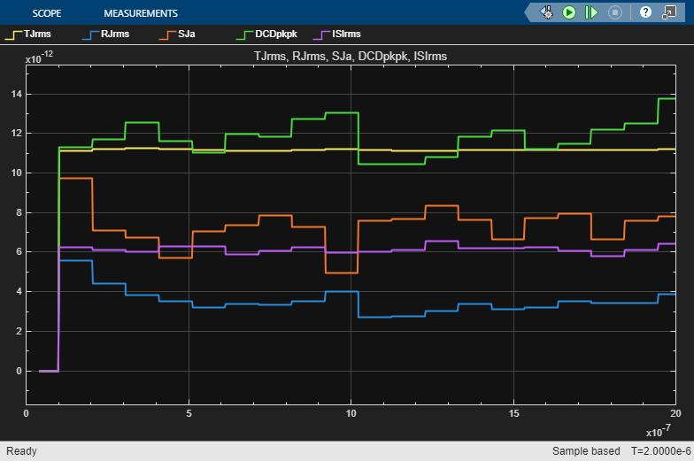
Run the simulation again and observe the results.
out = sim(model);
Note: If you do not provide the values for SymbolThresholds, ReferenceThresholds, SampleInterval, or SymbolTime, the function heuristically calculates these values.
This can increase the accuracy and consistency of the ISI characterization, which can in turn result in more accurate separation of jitter due to ISI and other jitter components (particularly RJ).