Calibrate Lidar-Camera Extrinsics Using MUN-FRL Dataset
R2026bThis example shows how to estimate the lidar-to-camera extrinsics in the MUN-FRL multi-sensor platform [1] using the Lidar Camera Calibrator (Point Cloud Toolbox) app. The lidar-to-camera 3-D transformation enables projecting lidar points into images or adding color from the images to the point clouds.
This example is part of the Calibrate a Multi-Sensor System Using MUN-FRL Dataset series. It requires the camera intrinsic parameters estimated in Calibrate Multi-Sensor Intrinsics Using MUN-FRL Dataset. The MUN-FRL platform uses a Velodyne VLP-16, which is a 16-beam lidar with a 30-degree vertical field of view. The limited number of beams and the narrow vertical field of view (FOV) make it challenging to calibrate the lidar-to-camera extrinsics:
The sparse point cloud produces few points on the calibration target, makes it challenging to accurately identify the corners of the calibration board since they are missing in the lidar scan.
The small overlapping FOV between the lidar and the down-facing camera limits the number of image-point cloud pairs where the calibration target is visible in both sensors.
Because of these constraints, you need to carefully select the parameters in the Lidar Camera Calibrator app to get enough detections. See Get Started with Lidar Camera Calibrator (Point Cloud Toolbox) for more information about using the app.
Download Calibration Data
Download the lidar camera calibration data from the MUN-FRL calibration dataset. The data folder contains synchronized pairs of images from the camera and point clouds from the lidar sensor in which the checkerboard is in the field of view of both sensors. You can either manually download the data or use the helperDownloadMUNFRLLidarCameraData function to download the files programmatically.
lidarCamFolder = helperDownloadMUNFRLLidarCameraData();
Lidar to Down-Facing Camera
Load Calibration Data
Open the Lidar Camera Calibrator app and add images and point clouds from the downloaded downLiCamCalibData20thMay2022_Trial5 folder.
lidarCameraCalibrator
Set the square size of the checkerboard to 70 mm and load the camera intrinsics from the intrinsicsDown.mat file created in the Calibrate Multi-Sensor Intrinsics Using MUN-FRL Dataset example.
Because the lidar and camera have a very narrow overlapping field of view, only a few valid image-point cloud pairs exist in this dataset. In most acquisitions, the checkerboard falls in the blind spot of the lidar sensor, where the board is not fully visible in the lidar scan. When this happens, the detected board corners are less accurate, which degrades the quality of the extrinsic calibration. Having fewer valid pairs also limits the diversity of board orientations available for calibration. For more accurate results:
Be aware of the viewing angle or the field of view of the lidar sensor. Do not place the board in the blind spots of the sensor.
Capture at least 10 acquisitions for accurate calibration.
For more best practices on collecting calibration data, see Data Collection Guidelines for Lidar-Camera Calibration (Point Cloud Toolbox).
Configure Checkerboard Detection
After adding the image and point cloud data, detect the calibration boards in the point cloud data automatically by setting the following parameters:
Cluster Threshold: If the distance between adjacent points is less than this threshold in meters, they belong to the same cluster. Although the VLP-16 lidar produces relatively sparse point clouds, the scene is cluttered with objects near the checkerboard, including the person holding it. Reduce this parameter from the default value to 0.09 so that the checkerboard is in its own cluster, distinct from nearby objects and the person.
Downsample Grid Size: Because the lidar sensor has only 16 beams, the point cloud is relatively sparse. To make full use of all the points, set this parameter to 0 to disable downsampling.
Ground Removal: In some point clouds, the checkerboard is placed very close to the ground. To avoid removing points that correspond to the checkerboard, disable this option.
Plane Fit Distance: A small plane fit distance helps get a tighter plane fit and to exclude noisy points from the detected checkerboard. Reduce the is parameter from the default value to 0.04.
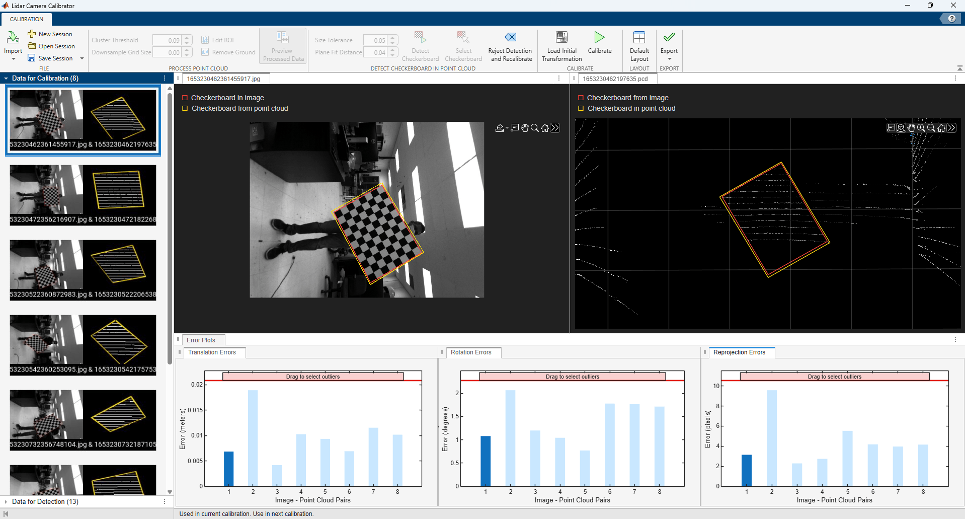
Click Detect Checkerboard. The app applies the updated parameters and shows the detected checkerboard borders in yellow. In total, 8 valid detections can be found with these parameters automatically. For this example, these are enough detections for accurate calibration. For other datasets, if you do not have enough detections for calibration, you can modify the parameter values to get more detections. Enable the Preview Processing Data button to visualize the effects of the processing steps in the point cloud data before detection. Alternatively, you can select the checkerboards manually.
Calibrate and Export Results
Click Calibrate to estimate the lidar camera extrinsics. After calibration, the app displays the alignment of the detected checkerboards in the image projected to the point cloud and the detected checkerboard in the point cloud projected to the image. This alignment gives you an indication of the accuracy of the calibration. The app also provides error metrics using translation and rotation error plots. The translation error is less than 2 centimeters and the rotation error is less than 2.5 degrees. You can exclude and reject data pairs with higher error metrics to improve calibration results. In this case, the calibration accuracy obtained with the 8 data pairs in the data for calibration browser is acceptable.
After calibration, click Export and export the calibration result to a file lidarToDownCamera.mat. The calibration result contains the lidar-to-camera transformation represented as a rigidtform3d object and the error metrics.
References
[1] Thalagala, Ravindu G., Oscar De Silva, Awantha Jayasiri, Arthur Gubbels, George KI Mann, and Raymond G. Gosine. "MUN-FRL: A visual-inertial-LiDAR dataset for aerial autonomous navigation and mapping." The International Journal of Robotics Research 43, no. 12 (2024): 1853-1866.
See Also
Topics
- Calibrate a Multi-Sensor System Using MUN-FRL Dataset
- Calibrate Multi-Sensor Intrinsics Using MUN-FRL Dataset
- Calibrate Camera-IMU Extrinsics Using MUN-FRL Dataset
- Create Multi-Sensor System from Pairwise Calibrations Using MUN-FRL Dataset
- Validate Calibration by Building a Colorized 3-D Map Using MUN-FRL Dataset

