Calibrate Camera-IMU Extrinsics Using MUN-FRL Dataset
R2026bThis example shows how to estimate the camera-to-IMU extrinsic transform in the MUN-FRL multi-sensor platform [1] using the estimateCameraIMUTransform (Navigation Toolbox) function. Unlike lidar camera calibration, this method does not require a static calibration target setup. Instead, it uses the motion of the sensor platform while observing a calibration pattern to estimate the spatial relationship between the two sensors.
This example is part of the Calibrate a Multi-Sensor System Using MUN-FRL Dataset series. It requires the camera intrinsic parameters estimated in Calibrate Multi-Sensor Intrinsics Using MUN-FRL Dataset example.
Download Calibration Data
Download the ROS bag files for the front-facing and down-facing cameras from the MUN-FRL calibration dataset. Each bag file contains synchronized camera images and IMU measurements recorded. You can either manually download the bag files from the dataset website or use the helperDownloadMUNFRLCameraIMUData helper function to download the files programmatically.
frontBagFile = helperDownloadMUNFRLCameraIMUData("front");
downBagFile = helperDownloadMUNFRLCameraIMUData("down");
Front-Facing Camera-IMU Extrinsics
The calibration data for the front camera is in a ROS bag file containing synchronized IMU measurements and camera images recorded while moving in front of an AprilGrid target.
Read Camera Images and IMU Measurements
Start by loading the ROS bag file and extracting the sensor data.
bagFront = rosbagreader(frontBagFile);
Read the IMU data from the /imu/data topic. Each message contains 3-axis accelerometer and gyroscope readings along with a timestamp. Store the measurements in a Create Timetables, which is the format required by the estimateCameraIMUTransform (Navigation Toolbox) function.
topicIMUFront = select(bagFront, "Topic","/imu/data");
imuMsgFront = readMessages(topicIMUFront,"DataFormat","struct");

% Extract accelerometer [m/s^2], gyroscope [rad/s], and timestamp.
% Convert ROS timestamps (seconds + nanoseconds) to absolute seconds.
numIMUFront = numel(imuMsgFront);
measFront = zeros(numIMUFront,7);
for i = 1:numIMUFront
    msg = imuMsgFront{i};
    measFront(i,:) = [msg.LinearAcceleration.X,msg.LinearAcceleration.Y,msg.LinearAcceleration.Z, ...
        msg.AngularVelocity.X,msg.AngularVelocity.Y,msg.AngularVelocity.Z, ...
        double(msg.Header.Stamp.Sec) + double(msg.Header.Stamp.Nsec)*1e-9];
end

% Create a timetable with Accelerometer and Gyroscope columns.
imuMeasurementsFront = timetable(measFront(:,1:3), measFront(:,4:6), RowTimes=datetime(measFront(:,7), ConvertFrom="posixtime"), ...
    VariableNames=["Accelerometer", "Gyroscope"]);
Read the grayscale camera images from the /front_camera/image_mono topic. Store the images in a 4-D array and record the timestamp for each frame.
topicFrontCam = select(bagFront, "Topic","/front_camera/image_mono");
msgFrontCam   = readMessages(topicFrontCam, DataFormat="struct");
numImagesFront= numel(msgFrontCam);

intrinsicsFront= load("intrinsicsFront.mat").intrinsicsFront;
imageSizeFront = intrinsicsFront.ImageSize;
frontCamImages = zeros(imageSizeFront(1), imageSizeFront(2), 1, numImagesFront, "uint8");
frontCamTime   = zeros(1, numImagesFront);
for i = 1:numImagesFront
    frontCamImages(:,:,:,i) = rosReadImage(msgFrontCam{i}, Encoding="mono8");
    frontCamTime(i) = double(msgFrontCam{i}.Header.Stamp.Sec) + double(msgFrontCam{i}.Header.Stamp.Nsec)*1e-9;
end

% Convert timestamps to datetime objects.
frontCamTime = datetime(frontCamTime, ConvertFrom="posixtime");
Estimate Camera Trajectory
Undistort the camera images using the intrinsic parameters estimated in the previous example. The undistortImage function removes lens distortion and returns updated intrinsics that reflect the undistorted image coordinates. These updated intrinsics are used in subsequent steps.
undistortedImagesFront = frontCamImages;
for i = 1:numImagesFront
    [undistortedImagesFront(:,:,:,i), newIntrinsicsFront] = undistortImage(frontCamImages(:,:,:,i), intrinsicsFront);
end
Display a subset of undistorted images.
subsetIndex = 1:200:numImagesFront;
figure(Position=[100 100 900 600])
tiledlayout(2, 3, TileSpacing="tight", Padding="tight");
for i = 1:numel(subsetIndex)
    nexttile
    imshow(undistortedImagesFront(:, :, :, subsetIndex(i)))
    title("Frame " + subsetIndex(i))
end
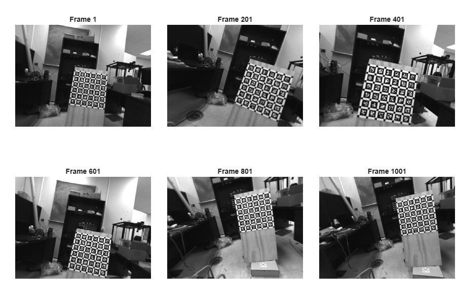
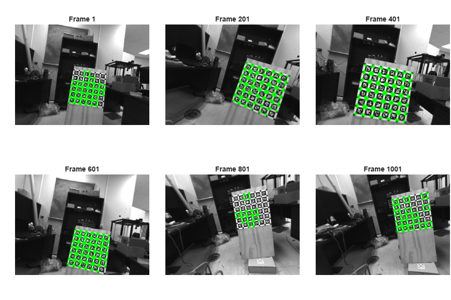
Detect the AprilGrid calibration pattern in the undistorted images. The AprilGrid used in this dataset is a 6-by-6 grid of AprilTag markers from the tag36h11 family. Each tag is 88 millimeters wide, and the spacing between tags is 30% of the tag size.
tagSize    = 0.088;        % Tag size in meters
tagSpacing = 0.3*tagSize;  % Gap between tags
patternDims= [6 6];        % Grid layout: rows-by-columns of tags
tagFamily  = "tag36h11";   % AprilTag family used

[patternDetectionsFront, imagesUsedFront] = detectAprilGridPoints(undistortedImagesFront, patternDims, tagFamily);

% Compute the 3-D world coordinates of the pattern corners.
patternPoints = patternWorldPoints("aprilgrid", patternDims, tagSize, tagSpacing);
Display the detected keypoints on a subset of images. Some images may not have all keypoints detected because of motion blur from the camera's fast movement.
figure(Position=[100 100 900 600])
tiledlayout(2, 3, TileSpacing="tight", Padding="tight");
for i = 1:numel(subsetIndex)
    nexttile
    imshow(undistortedImagesFront(:, :, :, subsetIndex(i)));
    hold on

    % Check if the image has valid detections
    if imagesUsedFront(subsetIndex(i))
        detIdx = sum(imagesUsedFront(1:subsetIndex(i)));
        plot(patternDetectionsFront(:, 1, detIdx), patternDetectionsFront(:, 2, detIdx), "g*");
    end
    title("Frame " + subsetIndex(i))
end
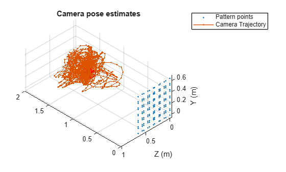
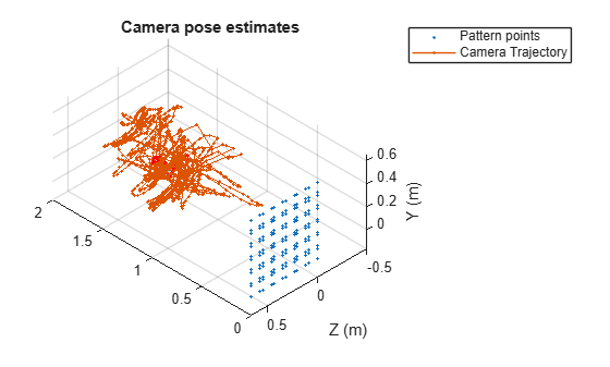
Estimate the camera pose for each image using the 3-D world point locations and detected 2-D keypoints. The pose describes the location and orientation of the camera relative to the calibration target. To obtain accurate estimates, use only images with at least 30 detected keypoints.
frontCamTimeUsed = frontCamTime(imagesUsedFront);
numValidImagesFront= nnz(imagesUsedFront);
frontCamPoses      = createArray(numValidImagesFront, 1, "rigidtform3d");
reprojectionErrorsFront = nan(numValidImagesFront,1);

ax = [];
minNumDetections = 30;
for imgId = 1:numValidImagesFront
    imagePoints = patternDetectionsFront(:, :, imgId);
    isValidPoints = ~isnan(imagePoints(:,1));
    if nnz(isValidPoints) >= minNumDetections
        % Estimate the camera extrinsics, which is the pattern-to-camera transform.
        extrinsics = estimateExtrinsics(imagePoints(isValidPoints, 1:2), patternPoints(isValidPoints,1:2), newIntrinsicsFront);

        % Convert extrinsics to pose, which is the camera-to-pattern transform.
        frontCamPoses(imgId) = extr2pose(extrinsics);

        % Compute reprojection error to assess pose accuracy
        worldPoints = [patternPoints(isValidPoints,1:2),zeros(nnz(isValidPoints),1)];
        projectedPoints = world2img(worldPoints, extrinsics, newIntrinsicsFront);
        reprojectionErrorsFront(imgId) = mean(vecnorm(projectedPoints-imagePoints(isValidPoints, 1:2),2,2));

        % Plot camera pose estimates
        ax = helperPlotCameraAndPattern(ax, patternPoints, frontCamPoses(imgId));
    end
end
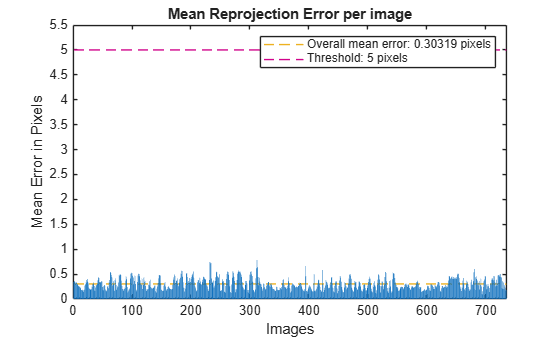
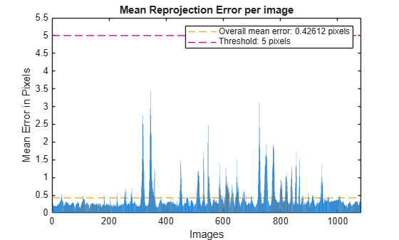
Filter out images with a mean reprojection error above 5 pixels. This threshold excludes frames with partially occluded targets or incorrect corner detections due to motion blur, while retaining enough data for calibration.
minReprojError = 5;
validImageIdsFront = reprojectionErrorsFront < minReprojError;

% Keep only valid data for calibration.
frontCamTimeValid = frontCamTimeUsed(validImageIdsFront);
frontCamPosesValid = frontCamPoses(validImageIdsFront);
patternDetectionsValidFront = patternDetectionsFront(:, :, validImageIdsFront);
The estimateCameraIMUTransform function models gyroscope bias as a slowly varying quantity bounded by the bias random walk noise. If the calibration sequence is too long, the accumulated bias drift can exceed these bounds, causing the solver to produce unreliable estimates. Trimming the data to a shorter window ensures the bias remains well-modeled while still providing enough motion excitation for an accurate calibration. In this example, the data is trimmed to 80 seconds.
maxDuration = seconds(80);
keepIdx = frontCamTimeValid - frontCamTimeValid(1) < maxDuration;
frontCamTimeValid = frontCamTimeValid(keepIdx);
frontCamPosesValid = frontCamPosesValid(keepIdx);
patternDetectionsValidFront = patternDetectionsValidFront(:,:,keepIdx);
Estimate Camera-IMU Transform
Configure the calibration options. The CameraInformation parameter is a 2-by-2 information matrix that weights the reprojection error residuals in the x and y pixel directions. Higher values indicate greater confidence in the camera pose estimates relative to IMU predictions. Reduce this value if camera poses are noisy due to a low-resolution calibration pattern or few detected keypoints.
calibOptions = cameraIMUCalibrationOptions(UndistortPoints=false, ImageTime=frontCamTimeValid, ...
    CameraPoses=frontCamPosesValid, CameraInformation=1e4*eye(2));
Load the IMU noise parameters. These include accelerometer and gyroscope noise densities and bias random walks, which are needed for IMU pre-integration during calibration.
imuParams = load("imuIntrinsics.mat").imuParams;Run the calibration. The estimateCameraIMUTransform function jointly optimizes camera poses, IMU pre-integrated trajectory, and the spatial transform between the two sensors. The camera-to-IMU extrinsics transform is returned as a se3 object.
[tformFront, paramsFront] = estimateCameraIMUTransform(patternDetectionsValidFront, patternPoints, ...
    imuMeasurementsFront, newIntrinsicsFront, imuParams, calibOptions);
Evaluate Calibration Accuracy
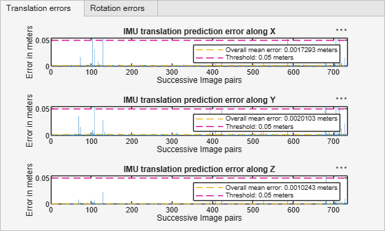
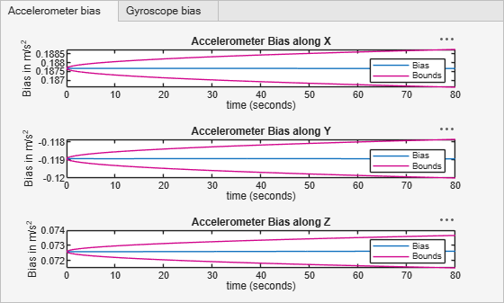
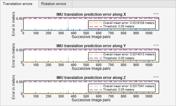
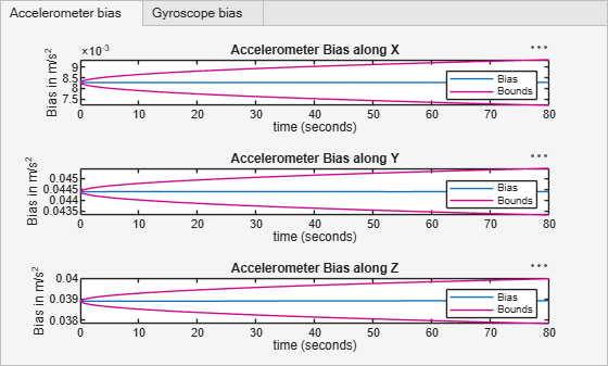
Evaluate the calibration using three diagnostic plots. The reprojection errors show per-image accuracy. All images should be within the threshold. The IMU prediction errors show how well the estimated IMU trajectory matches the camera poses. The bias estimates should remain within the modeled bounds over time, which are derived from the IMU intrinsic parameters. Together, these plots confirm the calibration is accurate.
showReprojectionErrors(paramsFront, Threshold=minReprojError);
showIMUPredictionErrors(paramsFront, Threshold=[0.05 0.05]);
showIMUBiasEstimates(paramsFront);
After calibration, save the estimated camera-to-IMU transform.
save("IMUtoCameraFront.mat", "tformFront")
Down-Facing Camera-IMU Extrinsics
Repeat the same calibration process for the down-facing camera: read data from the ROS bag, undistort images, detect the calibration pattern, estimate camera poses, and run the calibration.
Read Camera Images and IMU Measurements
Load the ROS bag file for the down-facing camera. Extract IMU measurements and camera images using the same procedure as the front camera.
bagDown = rosbagreader(downBagFile);
topicIMUDown = bagDown.select("Topic", "/imu/data");
imuMsgDown = readMessages(topicIMUDown, "DataFormat", "struct");

numIMUDown = numel(imuMsgDown);
measDown = zeros(numIMUDown, 7);
for i = 1:numIMUDown
    msg = imuMsgDown{i};
    measDown(i,:) = [msg.LinearAcceleration.X, msg.LinearAcceleration.Y, msg.LinearAcceleration.Z, ...
        msg.AngularVelocity.X, msg.AngularVelocity.Y, msg.AngularVelocity.Z, ...
        double(msg.Header.Stamp.Sec) + double(msg.Header.Stamp.Nsec)*1e-9];
end

imuMeasurementsDown = timetable(measDown(:,1:3), measDown(:,4:6), ...
    RowTimes=datetime(measDown(:,7), ConvertFrom="posixtime"), ...
    VariableNames=["Accelerometer", "Gyroscope"]);

% Read camera images from the /camera/image_mono topic.
topicDownCam = bagDown.select("Topic", "/camera/image_mono");
msgDownCam = readMessages(topicDownCam, DataFormat="struct");

intrinsicsDown = load("intrinsicsDown.mat").intrinsicsDown;
imageSizeDown = intrinsicsDown.ImageSize;

numImagesDown = numel(msgDownCam);
downCamImages = zeros(imageSizeDown(1), imageSizeDown(2), 1, numImagesDown, "uint8");
downCamTime   = zeros(1, numImagesDown);
for i = 1:numImagesDown
    downCamImages(:,:,:,i) = rosReadImage(msgDownCam{i}, Encoding="mono8");
    downCamTime(i) = double(msgDownCam{i}.Header.Stamp.Sec) + double(msgDownCam{i}.Header.Stamp.Nsec)*1e-9;
end
downCamTime = datetime(downCamTime, ConvertFrom="posixtime");
Estimate Camera Trajectory
Undistort the images, detect the AprilGrid pattern, and estimate camera poses for each frame. Filter out images with high reprojection error and trim the sequence to 80 seconds.
% Undistort images.
undistortedImagesDown = zeros(imageSizeDown(1), imageSizeDown(2), 1, numImagesDown, "uint8");
for i = 1:numImagesDown
    [undistortedImagesDown(:,:,:,i), newIntrinsicsDown] = undistortImage(downCamImages(:,:,:,i), intrinsicsDown);
end

% Detect AprilGrid pattern points.
[patternDetectionsDown, imagesUsedDown] = detectAprilGridPoints( ...
    undistortedImagesDown, patternDims, tagFamily);

% Estimate camera poses.
downCamTimeUsed    = downCamTime(imagesUsedDown);
numValidImagesDown = nnz(imagesUsedDown);
downCamPoses       = createArray(numValidImagesDown, 1, "rigidtform3d");
reprojectionErrorsDown = nan(numValidImagesDown, 1);

ax = [];
for imgId = 1:numValidImagesDown
    imagePoints = patternDetectionsDown(:, :, imgId);
    isValidPoints = ~isnan(imagePoints(:,1));
    if nnz(isValidPoints) >= minNumDetections
        % Estimate the camera extrinsics, which is the pattern-to-camera transform.
        extrinsics = estimateExtrinsics(imagePoints(isValidPoints, 1:2), patternPoints(isValidPoints, 1:2), newIntrinsicsDown);

        % Convert extrinsics to pose, which is the camera-to-pattern transform.
        downCamPoses(imgId) = extr2pose(extrinsics);

        % Compute reprojection error to assess pose accuracy
        worldPoints = [patternPoints(isValidPoints, 1:2), zeros(nnz(isValidPoints), 1)];
        projectedPoints = world2img(worldPoints, extrinsics, newIntrinsicsDown);
        reprojectionErrorsDown(imgId) = mean(vecnorm(projectedPoints - imagePoints(isValidPoints, 1:2), 2, 2));

        % Plot camera pose estimates
        ax = helperPlotCameraAndPattern(ax, patternPoints, downCamPoses(imgId));
    end
end
validImageIdsDown = reprojectionErrorsDown < minReprojError;

% Keep only valid data for calibration.
downCamTimeValid = downCamTimeUsed(validImageIdsDown);
downCamPosesValid = downCamPoses(validImageIdsDown);
patternDetectionsValidDown = patternDetectionsDown(:, :, validImageIdsDown);

% Use only the first 80 seconds of data to avoid gyroscope bias drift.
keepIdx = downCamTimeValid - downCamTimeValid(1) < maxDuration;
downCamTimeValid = downCamTimeValid(keepIdx);
downCamPosesValid = downCamPosesValid(keepIdx);
patternDetectionsValidDown = patternDetectionsValidDown(:,:,keepIdx);
Estimate Camera-IMU Transform
Configure the calibration options and run the calibration. The down-facing camera uses a higher CameraInformation value because the AprilGrid is closer to the camera and produces more accurate pose estimates.
calibOptions = cameraIMUCalibrationOptions(UndistortPoints=false, ImageTime=downCamTimeValid, ...
    CameraPoses=downCamPosesValid, CameraInformation=2e4*eye(2));

[tformDown, paramsDown] = estimateCameraIMUTransform(patternDetectionsValidDown, patternPoints, ...
    imuMeasurementsDown, newIntrinsicsDown, imuParams, calibOptions);
Evaluate Calibration Accuracy
Evaluate the calibration result using the same diagnostic plots as the front camera.
showReprojectionErrors(paramsDown, Threshold=minReprojError);
showIMUPredictionErrors(paramsDown, Threshold=[0.05 0.05]);
showIMUBiasEstimates(paramsDown);
Save the estimated camera-to-IMU transform.
save("IMUtoCameraDown.mat", "tformDown");
References
[1] Thalagala, Ravindu G., Oscar De Silva, Awantha Jayasiri, Arthur Gubbels, George KI Mann, and Raymond G. Gosine. "MUN-FRL: A visual-inertial-LiDAR dataset for aerial autonomous navigation and mapping." The International Journal of Robotics Research 43, no. 12 (2024): 1853-1866.
See Also
Topics
- Calibrate a Multi-Sensor System Using MUN-FRL Dataset
- Calibrate Multi-Sensor Intrinsics Using MUN-FRL Dataset
- Calibrate Lidar-Camera Extrinsics Using MUN-FRL Dataset
- Create Multi-Sensor System from Pairwise Calibrations Using MUN-FRL Dataset
- Validate Calibration by Building a Colorized 3-D Map Using MUN-FRL Dataset

