Main Content

filterOpenLoop

Create open-loop band pass filter in microstrip form

Since R2023a

Description

Use the filterOpenLoop object to create an open-loop bandpass filter in the microstrip form.
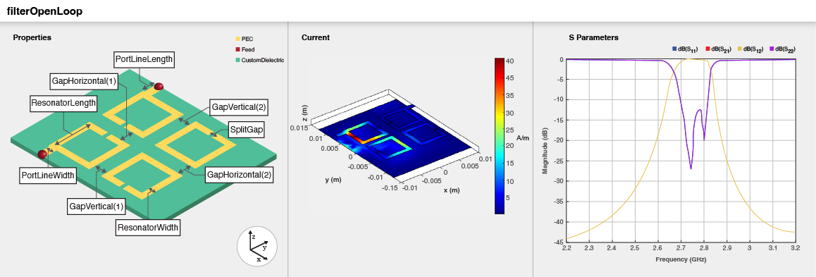
Three part image from right to left: Default image of an open-loop bandpass filter. Current distribution on the filter. S-parameters plot of the filter.

Creation

Description

filter = filterOpenLoop creates an open-loop bandpass filter with default properties for a cutoff frequency of 2.75 GHz.

example

filter = filterOpenLoop(Name=Value) sets Properties using one or more name-value arguments. For example, filterOpenLoop(ResonatorLength=0.008) creates an open-loop bandpass filter with resonator length of 8 cm. Properties not specified retain their default values.

example

Properties

expand all

Number of poles in the filter, specified as 4, 6, or 8.

Example: filter = filterOpenLoop(NumPoles=8)

Data Types: double

Length of resonator in meters, specified as a scalar.

Example: filter = filterOpenLoop(ResonatorLength=0.009)

Data Types: double

Width of resonator in meters, specified as a scalar.

Example: filter = filterOpenLoop(ResonatorWidth=0.002)

Data Types: double

Length of the split in the resonator in meters, specified as a scalar.

Example: filter = filterOpenLoop(SplitGap=0.0001)

Data Types: double

Horizontal gaps between the open-loop resonators of a quadruplet in meters, specified as one of these:

  • scalar

  • two-element vector when NumPoles is 2 or 4

  • four-element vector when NumPoles is 8

Example: filter = filterOpenLoop(GapHorizontal=[0.0033 0.0044])

Data Types: double

Vertical gaps between the open-loop resonators of a quadruplet in meters, specified as one of these:

  • scalar

  • two-element vector when NumPoles is 2 or 4

  • four-element vector when NumPoles is 8

Example: filter = filterOpenLoop(GapVertical=[0.0009 0.0008])

Data Types: double

Offset of the input and output feed lines in meters, specified as a scalar or a two-element vector. If you specify a scalar value, then input and output lines are offset by the same value. If you specify a two-element vector, the first element represents the offset for the input line and the second element the offset for the output line.

Example: filter = filterOpenLoop(FeedOffset=[0.0076 0.0096])

Data Types: double

Spacing between the quadruplet and input and output resonators in meters, specified as a scalar or a two-element vector. This property is enabled only when you set NumPoles to 6.

Example: filter = filterOpenLoop(CoupledResonatorGap=[0.0032 0.0042])

Data Types: double

Spacing between the two quadruplets in meters, specified as a scalar. This property is enabled only when you set NumPoles to 8.

Example: filter = filterOpenLoop(QuadrupletGap=0.00275)

Data Types: double

Offset the center of right side quadruplet along Y-axis in meters, specified as a scalar. This property is enabled only when you set NumPoles to 8

Example: filter = filterOpenLoop(QuadrupletOffset=0.3)

Data Types: double

Length of the input and the output line in meters, specified as a positive scalar.

Example: filter = filterOpenLoop(PortLineLength = 0.0035)

Data Types: double

Width of the input and the output line in meters, specified as a positive scalar.

Example: filter = filterOpenLoop(PortLineWidth = 0.001135)

Data Types: double

Height from the ground plane to the filter in meters, specified as a positive scalar.

Example: filter = filteropenLoop(Height = 0.00096)

Data Types: double

Width of the ground plane in meters, specified as a positive scalar.

Example: filter = filteropenLoop(GroundPlaneWidth = 0.00096)

Data Types: double

Type of dielectric material used as a substrate, specified as a dielectric object. The dielectric material in a filterOpenLoop object has these default properties: (Name='CustomDielectric',EpsilonR=10.8,LossTangent=0.0001,Thickness=1.27e-3)

Example: d = dielectric("FR4"); coupler = filterOpenLoop(Substrate=d)

Type of metal used in the conducting layers, specified as a metal object. The metal used in the conducting layers of filterOpenLoop object with default properties is PEC.

Example: m = metal("Copper"); coupler = filterOpenLoop(Conductor=m)

Data Types: string | char

Flag to add a metal shielding to the PCB component, specified as a logical 0 or logical 1. The default value is logical 0.

Example: IsShielded = true or 1 add a metal shield.

Note

To enable FEM solver required for the metal shield property, download the Integro-Differential Modeling Framework for MATLAB. To download this add-on:

  1. In the Home tab Environment section, click on Add-Ons. This opens the add-on explorer. You need an active internet connection to download the add-on.

  2. Search for Integro-Differential Modeling Framework for MATLAB and click Install.

  3. To verify if the download is successful, run

    matlab.addons.installedAddons
    in your MATLAB® session command line.

  4. On Windows, to run the IDMF add-on, you must install the Windows Subsystem for Linux (WSL). To install WSL, see Install Linux on Windows with WSL.

    The Windows Defender Firewall can block the PostgreSQL server when using the IDMF add-on. To resolve this issue, you can allow the server to communicate on desired networks if the firewall prompts. Alternatively, you can manually add the executable file of the PostgreSQL server located in <matlabroot>\sys\postgresql\win64\PostgreSQL\bin\postgres.exe. For more information, see https://support.microsoft.com/en-us/windows/risks-of-allowing-apps-through-windows-defender-firewall-654559af-3f54-3dcf-349f-71ccd90bcc5c.

Data Types: logical

This property is read-only.

Metal shield for the PCB component, specified as a shape.Box object. The length and width of the box must be equal to the length and width of the ground plane. The center of the box is at [0 0 Shielding.Height].

Dependencies

To enable the Shielding property, set the IsShielded property to true or 1.

Type of RF connector assembled at the feed locations of the PCB component, specified as a RFConnector object.

Example: Create connector from RFConnector object like this: coaxial = RFConnector adds a coaxial connector.

Dependencies

To enable the Connector property, set the IsShielded property to true or 1.

Object Functions

chargeCalculate and plot charge distribution
currentCalculate and plot current distribution
dgsCreate defected ground structure of PCB element
feedCurrentCalculate current at feed port
layoutPlot all metal layers and board shape
meshChange and view mesh properties of metal or dielectric in PCB component
shapesExtract all metal layer shapes of PCB component
showDisplay PCB component structure or PCB shape
sparametersCalculate S-parameters for RF PCB objects
RFConnectorCreate RF connector

Examples

collapse all

Create an open-loop filter with default properties.

filter = filterOpenLoop
filter = 
  filterOpenLoop with properties:

            NumPoles: 4
     ResonatorLength: 0.0070
      ResonatorWidth: 1.0000e-03
            SplitGap: 1.0000e-04
       GapHorizontal: 0.0022
         GapVertical: 8.0000e-04
          FeedOffset: 0.0066
       PortLineWidth: 0.0011
      PortLineLength: 0.0020
              Height: 0.0013
    GroundPlaneWidth: 0.0250
           Substrate: [1x1 dielectric]
           Conductor: [1x1 metal]
          SolverType: 'MoM'
          IsShielded: 0

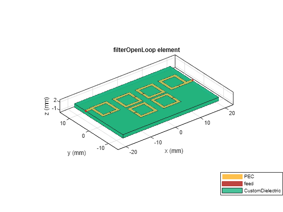
View the filter.

show(filter)

Figure contains an axes object. The axes object with title filterOpenLoop element, xlabel x (mm), ylabel y (mm) contains 6 objects of type patch, surface. These objects represent PEC, feed, CustomDielectric.

Create an open-loop filter with six poles and a different offset for the input and output lines.

filter = filterOpenLoop(NumPoles=6,FeedOffset=[0.0066,0.001]);

View the filter.

show(filter);

Figure contains an axes object. The axes object with title filterOpenLoop element, xlabel x (mm), ylabel y (mm) contains 6 objects of type patch, surface. These objects represent PEC, feed, CustomDielectric.

References

[1] Pozar, David M. Microwave Engineering. 4th ed. Hoboken, NJ: Wiley, 2012.

[2] Hong, Jia-Sheng, and M. J. Lancaster. Microstrip Filters for RF/Microwave Applications. Wiley, 2001.

[3] Pal Singh, Inder, Praveen Bhatt, Dinesh Bisht. "Design of Tunable Microstrip Bandpass Cascaded Quadruplet Filter". Advances in Computer Science and Information Technology (ACIST).Vol 2, Number 12, (July -September 2015) pp 11-14.

[4] Hong, Jia-Sheng, Michael J Lancaster. "Couplings of Microstrip Square, Open-Loop Resonators or Cross-Coupled Planar Microwave Filters". IEEE Transactions on Microwave Theory and Techniques.Vol 44, Number 12, (December 1996).

Version History

Introduced in R2023a

expand all