Generate Standalone ROS 2 Node from Simulink
This example shows you how to generate and build a standalone ROS 2 node from a Simulink® model. The process starts with generating C++ code in Simulink for a proportional controller model. Next, the code is built and executed as a ROS 2 node on the remote device. The deployed node is then used to control a differential-drive robot equipped with ROS 2 capabilities.
Prerequisites
This example requires Simulink Coder™.
Set up Docker® in your host environment (Windows Subsystem for Linux (WSL), Linux® or Mac) and create a Docker image for Gazebo. For more information on how to configure Docker, see Install and Set Up Docker for ROS, ROS 2, and Gazebo.
Review the Feedback Control of a ROS-Enabled Robot over ROS 2 example.
See ROS 2 Model Build Failure in ROS and ROS 2 Simulink Support and Limitations.
To ensure you have the proper third-party software, see ROS Toolbox System Requirements.
Start Docker Container
With the prerequisites set up and the Docker image created, the first step is to launch an instance of Docker container.
To start a Docker container, run the following command in WSL/Linux/Mac terminal:
$ docker run -it --net=host -v /dev/shm:/dev/shm --name sl_ros_controller <image-name>
Here, 'sl_ros_controller' is the name of the Docker container. Replace the <image-name> with the name of the Docker image created in the prerequisite section.
Get IP Address of Docker Container
While the Docker container is running, obtain the IP address of the Docker container running on the remote device. This IP address is necessary for establishing an SSH connection and accessing the Gazebo simulator. Note that the IP address of the Docker container is the same as the IP of the host machine.
To retrieve this IP address, run the following command in the WSL/Linux/Mac terminal:
$ ifconfig

The connection type can vary depending on how you are connected to the host. In this case use the Ethernet (eth0), however, in many cases the wireless (wlan0) is the appropriate connection.
Start Gazebo Robot Simulator
Once the container is running, start the Gazebo robot simulator inside the Docker container.
Open a terminal within the Docker container by executing the following command in the WSL/Linux/Mac terminal:
$ docker exec -it sl_ros_controller /bin/bash
Here, 'sl_ros_controller' is the name of Docker container.
In the Docker container terminal, launch the TurtleBot in a Gazebo world by running the following command:
$ source start-gazebo-empty-world.sh
To view the Gazebo world, open a web browser on your host machine and connect to the URL <docker-ip-address>:8080. If Docker is running on your host machine, you can simply use localhost:8080. You can now visualize and interact with the Gazebo world directly in your web browser.

Configure Proportional Controller Model for Code Generation
Configure robotControllerROS2 model to generate C++ code for a standalone ROS 2 node. The model is the proportional controller introduced in the Feedback Control of a ROS-Enabled Robot over ROS 2 example.
Open the robot feedback control model configured for ROS 2. Alternatively, call
open_system("robotControllerROS2").Under ROS tab, in Prepare, click Hardware settings. In the Hardware implementation pane, Hardware board settings section contains settings specific to the generated ROS 2 package, such as information to be included in the
package.xmlfile. Change Maintainer name toROS 2 Example User.The model requires variable-size arrays. To enable this option, check variable-size signals under Code Generation > Interface > Software environment.
In the Solver pane, ensure that Solver Type is set to Fixed-step, and set Fixed-step size to
0.05. In generated code, the Fixed-step size defines the actual time step, in seconds, that is used for the model update loop (see Execution of Code Generated from a Model (Simulink Coder)). It can be made smaller (e.g., 0.001 or 0.0001) but for current purposes 0.05 is sufficient.Specify external ROS packages as dependencies: To specify external ROS 2 packages as dependencies to the generated ROS 2 node, specify appropriate toolchain options. In the Configuration parameters, under Code Generation > Toolchain Settings, specify the Build configuration as Specify from the drop-down. Then, you can specify the Required Packages, Include Directories, Link Libraries, Library Paths and Defines based on the external ROS 2 packages that you want to integrate with the generated ROS 2 node.
Specify custom source and include files: You can specify custom source and include files in the configuration parameters, under Simulation Target > Custom Code. In the Code Information section, specify Include headers, Include directories and Source files. In the configuration parameters, under Code Generation > Custom Code, select Use the same custom code settings as Simulation Target.
Click OK.
Configure Connection with ROS 2 Device
A ROS 2 device is any Linux system that has ROS 2 installed and is capable of building and running a ROS 2 node. If you have Simulink Coder, you can generate code for a standalone ROS 2 node. If your system is connected to a ROS 2 device, Simulink can also transfer the generated code to the ROS 2 device, build an executable, and run the resulting ROS 2 node (this is referred to as "deploying" the ROS node).
In this task, you decide if you want to generate code for the ROS 2 node or if you want to build and run it on a ROS 2 device. If you are connected to a ROS 2 device, you can configure Simulink to use it as a deployment target for your ROS 2 node.
Under the Modeling tab, click Model Settings.
In the Hardware Implementation pane of Configuration Parameters dialog box, select an Build action under Hardware board settings > Target hardware resources > Groups > Build Options. The selected build action affects the behavior of Simulink when building the model. None (the default setting) only generates the code for the ROS 2 node, without building it on an external ROS 2 device. Build and load generates the code, transfers it to an external device and builds a ROS 2 node executable. If you select Build and run, the resulting node executable is started automatically at the end of the build.
Set the Build action to Build and run.
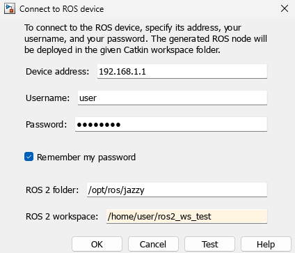
Configure the connection to your external ROS 2 device. Under the ROS tab, from the Deploy to drop-down, click Manage Remote Device. This opens the Connect to a ROS device dialog box. In this dialog box, you can enter all the information that Simulink needs to deploy the ROS 2 node. This includes the IP address or host name of your ROS 2 device, your login credentials, and the ROS 2 workspace.
You'll use the following credentials to connect to the Docker container (remote device):
Device address: the IP address of Docker container
Username: '
user'Password: '
password'ROS 2 folder:
/opt/ros/jazzyROS 2 workspace:
/home/user/ros2_ws_test
ROS 2 Folder is the location of the ROS 2 installation on the ROS 2 device. If you do not specify this folder, the settings test (see next step) tries to determine the correct folder for you.
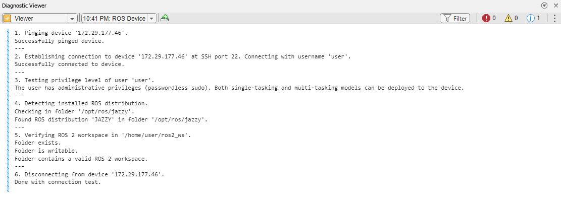
If the ROS 2 device is turned on and accessible from your computer, you can verify the connection settings by clicking Test. The test verifies every device setting and display warnings and errors in the Simulink Diagnostic Viewer if problems are found. If possible, the test also suggests how the problems can be fixed. Click Test now.
Most likely, the ROS 2 workspace
~/ros2_ws_testdoes not exist on the target device. The test detects this problem and suggests to create the folder and initialize the workspace. Click Fix to apply this action automatically. After a few seconds, you should see a green notice that the folder has been created successfully. In the following figure you can see an example of creating the folder successfully. To verify that the Catkin workspace is now available, click Test in the connection settings dialog box again. The warning has disappeared and the Catkin workspace is ready to build your ROS 2 node.
Change the device connection settings and test them until no other warnings or errors are shown. If an automatic fix to your settings is possible, Simulink suggests it by displaying the Fix button. Once you have a good set of settings, click OK in the connection settings dialog box to save the settings.
The connection settings are not specific to a single model, but apply to all ROS 2 models in Simulink.
Generate Source Code for ROS 2 Node
In this task, you generate code for a standalone ROS 2 node, and automatically build, and run it on the host computer.
In MATLAB®, change the current folder to a location where you have write permission.
Under the Simulation tab, in Prepare, select ROS Toolbox > ROS Network.
Set the Domain ID (ROS 2) of ROS 2 network. This example uses Domain ID as 25.
If you are deploying to a local device, set the environment variable
ROS_DOMAIN_IDto the value 25, usingsetenvin MATLAB.Set the ROS Middleware (ROS 2) of ROS 2 network. This example uses ROS Middleware as .
If you are deploying to a local device, set the environment variable
RMW_IMPLEMENTATIONtormw_fastrtps_cpp, usingsetenvin MATLAB.Under ROS tab, from the Deploy Type section, select the deployment type as Standard Node.
In ROS tab, from the Deploy section dropdown, click Build & Run. If you get any errors about bus type mismatch, close the model, clear all variables from the base MATLAB workspace, and re-open the model. Click on the View Diagnostics link at the bottom of the model toolbar to see the output of the build process.
Once the code generation completes, the ROS 2 node builds in the present working folder starts to run automatically in a synchronous fashion based on the sample time of the model. When running in Windows®, a Command window opens. Do not close the window, but use Ctrl+C to shutdown the ROS 2 node.
Use ros2 node to list all running nodes is the ROS 2 network. robotControllerROS2 should be in the displayed list of nodes.
setenv('ROS_DOMAIN_ID', '25')
ros2('node','list')
Verify that the deployed node publishes data on the ROS 2 topic, /cmd_vel, to control the motion of simulated robot.
ros2('topic','list')
/camera/camera_info
/camera/image_raw
/camera/image_raw/compressed
/camera/image_raw/compressedDepth
/camera/image_raw/theora
/camera/image_raw/zstd
/clock
/cmd_vel
/imu
/joint_states
/odom
/parameter_events
/robot_description
/rosout
/scan
/tf
/tf_static
Specify Code Generation and Build Options
You can choose different code generation and build behaviors by specifying one of these Deployment options from the toolstrip under ROS tab.
Generate code — Generates the ROS package source code on localhost or remote device.
Build Model — Generates the ROS package source code and builds the standalone executable on localhost or remote device.
Build & Run — Generates the ROS package source code, builds the standalone executable and starts running it on localhost or remote device.