Channel Emulation on NI USRP Radio
R2026bThis example shows how to deploy a multipath channel emulation algorithm on the FPGA of an NI™ USRP™ radio. The channel emulator applies per-path fractional and integer delays and complex gains to an input signal, enabling real-time emulation of frequency-selective multipath channels for over-the-air testing.
Workflow
In this example, you follow a step-by-step guide to generate a custom FPGA image from a Simulink® model and deploy it on an NI USRP radio by using a generated MATLAB® host interface script.
For more information about how to prototype and deploy software-defined radio (SDR) algorithms on the FPGA of an NI USRP radio, see Target NI USRP Radios Workflow.
Design Overview
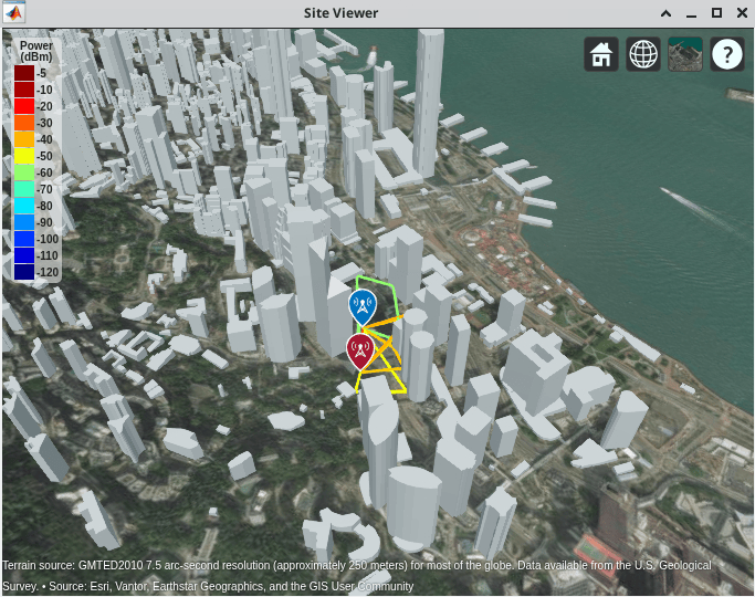
The channel emulator receives an input signal from a radio antenna, applies multipath channel effects, and retransmits the modified signal through a second antenna. The FPGA implements a single-input single-output (SISO) multipath channel filter that processes up to 11 propagation paths simultaneously. Each path applies a programmable fractional delay using a 16-tap polyphase FIR filter, an integer sample delay, and a complex path gain. The algorithm sums across all paths to produce the channel-filtered output. This example uses a ray tracing channel model based on a Hong Kong urban scenario to define the propagation paths with realistic delays and gains.
From the host, you program the path delays and complex gains using streaming interfaces. You can generate fading channel effects by reprogramming the channel model at run time without regenerating the bitstream.
By deploying a channel emulator on the FPGA, you can create a controlled test environment for repeatable over-the-air testing without a live propagation channel. This approach enables you to reproduce specific propagation conditions in the lab and apply identical channel profiles across test runs for consistent performance comparisons.
Requirements
To target NI USRP radio devices with Wireless Testbench™, you must install and configure third-party tools and additional support packages.
For details about which NI USRP radios you can target, see Supported Radio Devices.
Note
You cannot use this example with a USRP X310 radio with TwinRX daughterboards. The design in this example requires a transmit path.
This workflow supports generating bitstreams only on a Linux® operating system (OS). For details about host system requirements, see System Requirements.
For details about how to install and configure additional support packages and third-party tools, see Installation for Targeting NI USRP Radios.
Set Up Environment and Radio
Set up a working directory for running the example by using the
openExample function in MATLAB. This function downloads the example files into a subfolder of the
Examples folder in the currently running release and then opens the
example. If a copy of the example exists, openExample opens the existing
version of the example.
openExample("wt/ChannelEmulationOnNIUSRPRadioExample")The working folder contains all the files you need to use this example, including helper functions and supporting files. The files you interact with are:
wtChannelEmulatorSL.slx— The Simulink hardware generation model. This model includes theChannelEmulatorDUT subsystem, which implements a multipath channel filter, and additional subsystems that enable you to simulate the DUT behavior.ChannelEmulationOnNIUSRPRadioExample.m— The MATLAB script that you can use to simulate the behavior of the Simulink model before you generate HDL code.VerifyChannelEmulationAlgorithmUsingMATLABExample.m— A live script that you can use in MATLAB to verify the algorithm running on your radio.
To program the FPGA on your radio with the bitstream that you generate in this example, and to verify the algorithm running on your radio, use the Radio Setup wizard to connect and set up your radio.
Simulink Hardware Generation Model
The Simulink model in this example implements a SISO multipath channel emulator using a hardware modeling style and uses blocks that support HDL code generation. The model applies per-path fractional and integer delays, multiplies each path by a complex gain, and sums across all paths to produce a single filtered output. It uses fixed-point arithmetic and has streaming interfaces for data, path gain, and path delay programming inputs.
Open Model
Open the Simulink model.
open_system('wtChannelEmulatorSL');
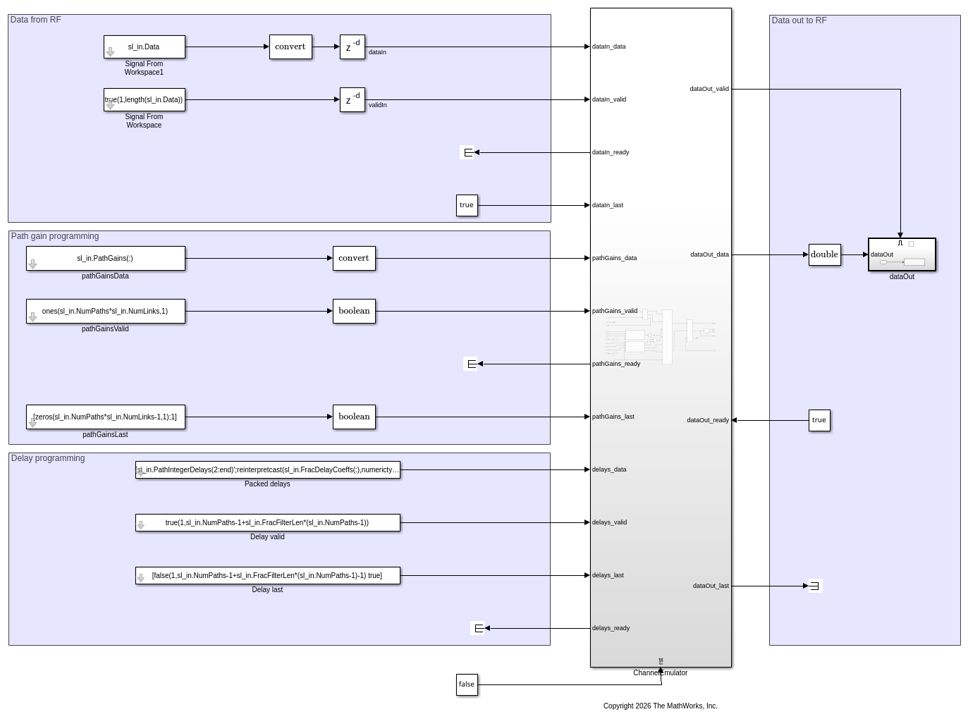
The top-level structure of the model includes the ChannelEmulator subsystem, which is the DUT. It also contains subsystems and blocks that generate input data and save output data for simulating the behavior of the DUT.
Open the ChannelEmulator subsystem.
open_system('wtChannelEmulatorSL/ChannelEmulator');
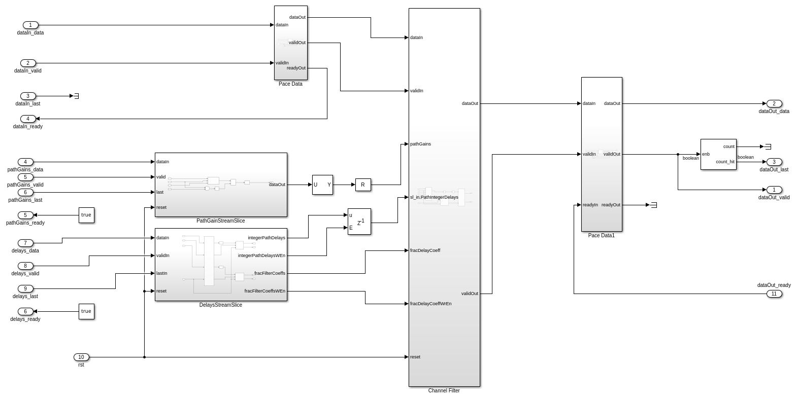
Data flows through these blocks and subsystems:
The
DelaysStreamSlicesubsystem deserializes the streaming path delay programming input. It converts serial streams into parallel integer path delays and fractional delay filter coefficients for theChannel Filtersubsystem.The
PathGainControlsubsystem buffers the streaming complex path gains. It presents them as a parallel vector synchronized with the data valid signal.The
Channel Filtersubsystem is the core signal processing block. It applies per-path fractional and integer delays, multiplies each delayed path by its complex gain, and sums across all paths.
Open the Channel Filter subsystem.
open_system('wtChannelEmulatorSL/ChannelEmulator/Channel Filter');
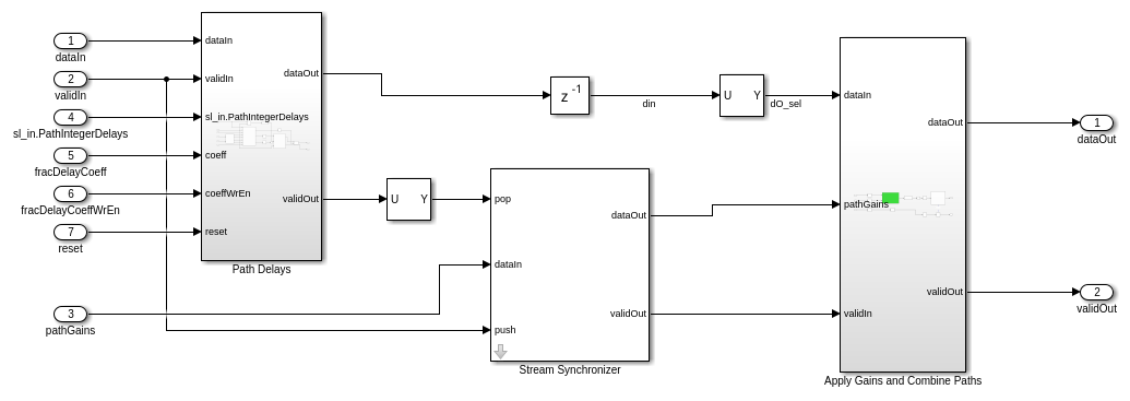
The Channel Filter subsystem accepts data, path gains, integer path delays, and fractional delay coefficients. It processes the input through two stages:
The
Path Delayssubsystem applies both a fractional delay (polyphase FIR filter) and an integer sample delay to each propagation path independently.The
Apply Gains and Combine Pathssubsystem multiplies each delayed path signal by its corresponding complex path gain and sums the contributions from all paths into a single output stream.
Open the Path Delays subsystem.
open_system('wtChannelEmulatorSL/ChannelEmulator/Channel Filter/Path Delays');
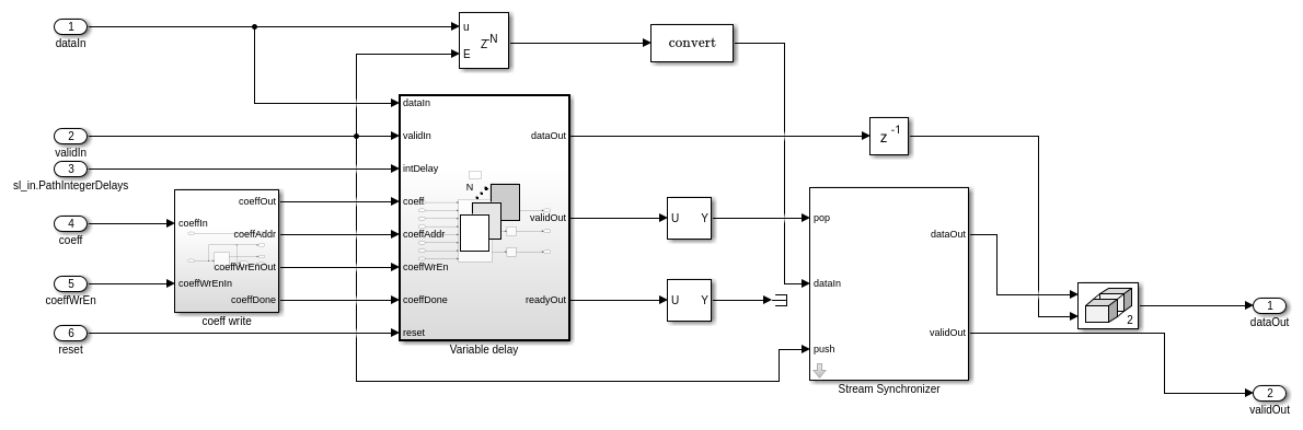
This subsystem implements per-path delay processing using a For Each Subsystem block that processes each path independently. For each path, the processing chain is:
A programmable FIR filter implements the fractional sample delay. The filter uses 16 taps with coefficients derived from a polyphase decomposition with 50 interpolation phases. The
coeff writeblock manages writing new filter coefficients when the channel is reprogrammed.A variable-length memory implements the integer sample delay. The delay value is programmable through the
intDelayport.
The first path, which is the reference path, has zero fractional delay and passes through a stream synchronizer to align with the delayed paths for downstream processing.
Open the Apply Gains and Combine Paths subsystem.
open_system('wtChannelEmulatorSL/ChannelEmulator/Channel Filter/Apply Gains and Combine Paths');
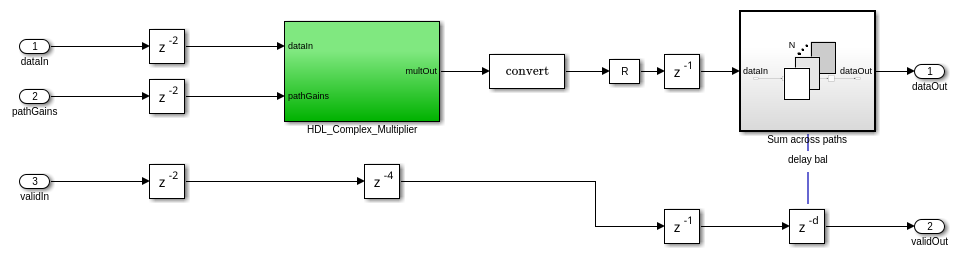
This subsystem performs two operations:
The HDL_Complex_Multiplier block multiplies each path's delayed signal by its corresponding complex path gain. The multiplier uses a pipelined architecture suitable for HDL code generation.
The Sum across paths block accumulates the weighted contributions from all paths into a single output sample representing the channel-filtered signal.
Simulate Design
Verify the design by simulating the model and comparing the results against the MATLAB floating-point golden reference. Set up the simulation parameters using the helperChannelEmulatorSimulationSetup function with the ray tracing channel model. This function configures 11 static propagation paths from a Hong Kong urban scenario. It generates 4-QAM test data and designs the polyphase fractional delay filter coefficients.
sl_in = helperChannelEmulatorSimulationSetup;
Display the key simulation parameters.
fprintf('Sample Rate:            %.0f MHz\n', sl_in.SampleRate/1e6);
fprintf('Number of Paths:        %d\n', sl_in.NumPaths);
fprintf('Frame Length:           %d samples\n', sl_in.FrmLen);
fprintf('Fractional Filter Taps: %d\n', sl_in.FracFilterLen);
Sample Rate:            250 MHz
Number of Paths:        11
Frame Length:           1000 samples
Fractional Filter Taps: 16
Compute a golden reference output using the comm.ChannelFilter System object™. This System object implements the same multipath channel filtering in MATLAB. It serves as a behavioral reference for the fixed-point Simulink model.
chanFilter = comm.ChannelFilter( ...
    SampleRate=sl_in.SampleRate, ...
    PathDelays=sl_in.PathDelays, ...
    NormalizeChannelOutputs=false, ...
    FilterDelaySource='Custom', ...
    FilterDelay=sl_in.FracFilterLen/2 - 1);
yGolden = chanFilter(sl_in.Data, sl_in.CIR);
Simulate the model.
simTime = (1.5 * sl_in.FrmLen / sl_in.SampleRate) * sl_in.OversampleFactor;
out = sim('wtChannelEmulatorSL', 'StopTime', num2str(simTime));
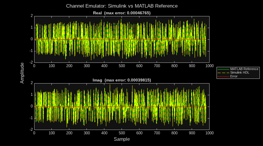
Compare the Simulink fixed-point output against the MATLAB floating-point golden reference. The plot shows the real and imaginary components of both signals overlaid, along with the error signal highlighting quantization differences.
ySimulink = out.hdlchanfilt(:);
sigLen = min(length(ySimulink), length(yGolden));
ySimulink = ySimulink(1:sigLen);
yGolden = yGolden(1:sigLen);
sigErr = ySimulink - yGolden;

maxErrRe = max(abs(real(sigErr)));
maxErrIm = max(abs(imag(sigErr)));

figure(Position=[100 100 900 500]);
tl = tiledlayout(2, 1);
title(tl, "Channel Emulator: Simulink vs MATLAB Reference");
xlabel(tl, "Sample");
ylabel(tl, "Amplitude");

nexttile;
plot(real(yGolden), '-g');
hold on
plot(real(ySimulink), '--y');
plot(real(sigErr), '-r')
hold off
title("Real  (max error: " + num2str(maxErrRe) + ")");

nexttile;
plot(imag(yGolden), '-g');
hold on
plot(imag(ySimulink), '--y');
plot(imag(sigErr), '-r')
hold off
title("Imag  (max error: " + num2str(maxErrIm) + ")");

leg = legend(["MATLAB Reference", "Simulink HDL", "Error"]);
leg.Layout.Tile = 'east';
Configure IP Core
When you are satisfied with the simulated behavior of the model, you can proceed to integrate your design into a custom IP core by generating HDL code and mapping the model inputs and outputs to the hardware interfaces.
First, use the hdlsetuptoolpath (HDL Coder) function to set up the
tool chain. Specify the path to your Vivado® bin directory. For more information, see Set Up Third-Party Tools.
hdlsetuptoolpath('ToolName','Xilinx Vivado', ...
    'ToolPath','/opt/Xilinx/Vivado/2021.1/bin');
From the Apps tab in the Simulink Toolstrip, select HDL Coder. Then open the HDL Code tab.
Configure Output Options
In the HDL Code tab, configure the output options:
Ensure the
ChannelEmulatorsubsystem is pinned in the Code for option. To pin this selection, select theChannelEmulatorsubsystem in the Simulink model and click the pin icon.Select IP Core as the Output > IP Core option.

Configure HDL Code Generation Settings
Open the Configuration Parameters dialog box by clicking Settings in the HDL Code tab.
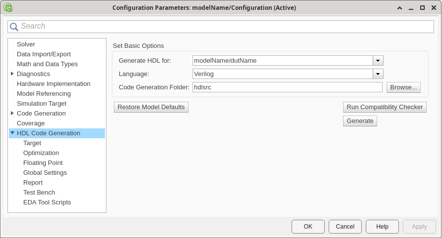
In the HDL Code Generation pane, ensure that Language is set to Verilog. By default, HDL Coder generates the Verilog® files in the hdlsrc folder. You can select an alternative location. If you make any changes, click Apply.
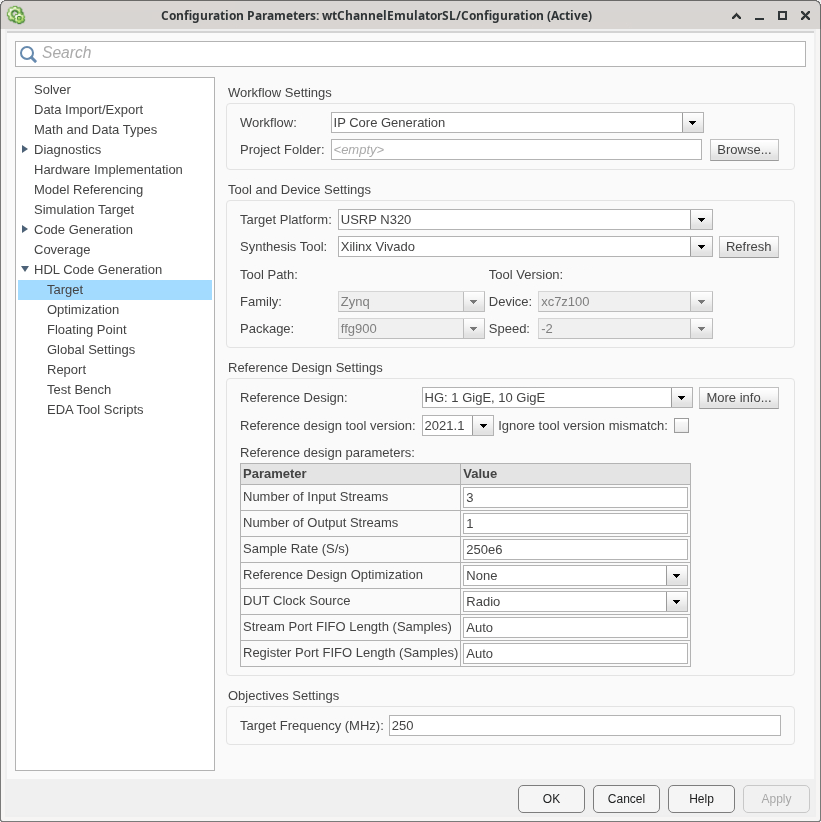
In the Target pane, configure these settings:
Under Workflow Settings, select the
IP Core
                        Generation
workflow. To set Project Folder, click Browse and select a target location for saving the generated project files. If you do not specify a project folder, the software saves the generated project files in the working directory.Under Tool and Device Settings, select your radio from the Target Platform list. This example uses a USRP N320 radio. If you are using a different radio, adjust the reference design parameters.
Under Reference Design Settings, set Reference Design to
HG: 1 GigE, 10GigE.Set the reference design parameters to these values:
Number of Input Streams — Set to
3because the DUT has three input streams: one data stream from a radio antenna, one for programming the path gains, and one for programming the path delays.Number of Output Streams — Set to
1because the DUT sends one data output stream to a radio antenna for transmission.Sample Rate (S/s) — Set to a sample rate supported by your radio configuration. The channel emulation algorithm operates at the master clock rate (MCR). The verification script uses the sample rate returned by the
helperChannelEmulatorSimulationSetupfunction.Reference Design Optimization — Set to
None. This setting preserves all reference design resources for maximum debugging capability during initial development.DUT Clock Source — Set to
Radio. When you select this setting, the DUT is clocked at the MCR used by the radio to achieve the specified sample rate.Stream Port FIFO Length (Samples) — Set to
Auto. This setting automatically calculates the buffer length for each DUT input and output data streaming port.Register Port FIFO Length (Samples) — Set to
Auto. This setting automatically calculates the buffer length for each DUT register port.
Click Apply.
For more information, see Configure HDL Code Generation Settings.
Map Target Interfaces
In the HDL Code tab, click Target Interface
to open the Interface Mapping table in the IP Core editor. To
populate the table with your user logic, click the Reload IP core settings button:  .
.
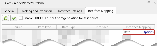
The Source, Port Type, and Data Type columns are populated based on the Simulink model. In this example, the Interface column is prepopulated because the model is saved with the interface mapping already assigned.
The
rstinput register port maps to aWrite Registerinterface.The RF data input (
dataIn,dataIn_valid,dataIn_last,dataIn_ready) map to aStream Port Input0interface. This stream carries the input signal from the receive antenna to the channel emulator.The RF data output (
dataOut,dataOut_valid,dataOut_last,dataOut_ready) map to aStream Port Output0interface. This stream carries the channel-filtered signal to the transmit antenna.The
pathGains_dataanddelays_dataports map to additionalStream Port Inputinterfaces. These streaming interfaces accept the channel model path gains and delays from the host.
The Interface Mapping column is populated automatically based on the signal names in the model.
To set the interface options for the data streaming interfaces, open the Set Interface Options window by clicking Options in the far right of the table.
For the
dataIninterface options, select the first enumerated receive antenna as the source connection. For example, on a USRP N320 radio, selectRF0:RX2. The DUT receives input samples from this antenna on the radio.For the
dataOutinterface options, select the second enumerated transmit antenna as the sink connection. For example, on a USRP N320 radio, selectRF1:TX/RX. The DUT sends the channel-filtered output samples to this antenna for transmission.For the
pathGains_dataanddelays_datainterface options, selecthostas the source connection.
When you have populated the table, validate the interface mapping by clicking the
Validate IP core settings button:  .
.
For more information, see Map Target Interfaces.
Generate and Load Bitstream
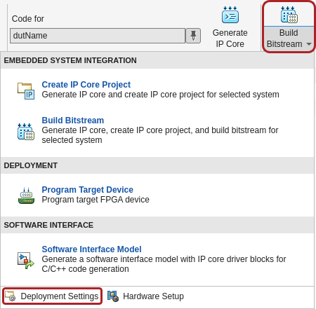
To generate a bitstream from the configured IP core, select Build Bitstream > Deployment Settings.
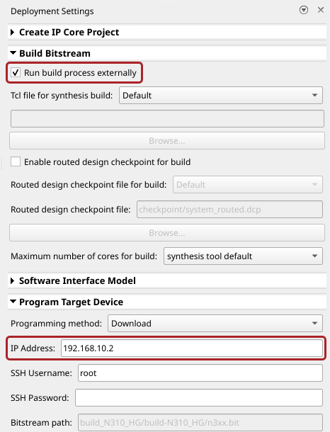
Ensure that the Run build process externally option is selected. This setting is the default and it ensures that the bitstream build executes in an external shell, which allows you to continue using MATLAB while building the FPGA image.
In the Program Target Device settings, set the IP address. The default is
192.168.10.2. If your radio has a different IP address, update this value.
Click Build Bitstream to create a Vivado IP core project and build the bitstream. After the basic project checks
complete, the Diagnostic Viewer displays a Build Bitstream Successful
message along with warning messages. However, you must wait until the external shell
displays a successful bitstream build before moving to the next step. Closing the external
shell before this time terminates the build.
The bitstream for this project generates with the name n3xx.bit and
is located in the build_N320_HG/build-N320_HG folder of the working
directory after a successful bitstream build. If you are using a different radio, the name
and location reflect your radio.
To load the bitstream onto the device now, select Build Bitstream > Program Target Device. Alternatively, you can load the bitstream later by using the
programFPGA function in the generated host interface script.
For more information, see Generate Bitstream and Program FPGA.
Generate Host Interface Scripts
To generate MATLAB scripts that enable you to connect to and run your deployed design on your radio, in the HDL Code tab, click Host Interface Script. This step generates two scripts in your working directory based on the target interface mapping that you configured for your IP core.
gs_wtChannelEmulatorSL_interface.m— Host interface script that creates anfpgaobject for interfacing with your DUT running on the FPGA from MATLAB. The script contains code that connects to your hardware and programs the FPGA and code samples to get you started with running the algorithm on your radio. For more information, see Interface Script File.gs_wtChannelEmulatorSL_setup.m— Setup function that configures thefpgaobject with the hardware interfaces and ports from your DUT algorithm. The function contains DUT port objects that have the port name, direction, data type, and interface mapping information, which it maps to the corresponding interfaces. For more information, see Setup Function File.Note
The number of samples per host-side
readPortorwritePortoperation, specified in theFrameSizename-value argument of theaddRFNoCStreamInterfacefunction, is set by default to 1e5. To change this value or the value of theTimeoutname-value argument, edit the setup function file.
Edit Setup Function File
The generated setup function file configures the streaming interfaces with the
default frame size of 1e5 samples. Before you run the verification
script, update the frame sizes for the pathGains_data and
delays_data streaming inputs by following these steps.
Open the setup function file for editing.
edit gs_wtChannelEmulatorSL_setup.mIdentify the calls to the
addRFNoCStreamInterfacefunction for thepathGains_dataanddelays_dataports.Update the
FrameSizevalue forpathGains_datato11. This value equals the number of channel paths, because the host sends one complex gain per path.TX_STREAM0_FrameSize = 11;
Update the
FrameSizevalue fordelays_datato170. This value accounts for the 10 integer path delays (paths 2 through 11, because path 1 is the zero-delay reference) plus 160 fractional delay filter taps (16 taps for each of the 10 paths).TX_STREAM1_FrameSize = 170;
Save the updated setup function file.
Verify Channel Emulation Algorithm Using MATLAB
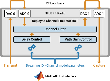
Use this script to verify the channel emulation algorithm running on your radio. Program the FPGA with a ray tracing channel model and compare the hardware output against a MATLAB reference.
This script follows these steps:
Set up and configure the radio with the generated bitstream and interfaces.
Set up channel parameters for running on hardware at the device sample rate.
Program the channel emulator with path delays and gains from a ray tracing scenario.
Validate the impulse response of the FPGA against the
comm.ChannelFilterSystem object.Verify the frequency-selective behavior by comparing input and output power spectra.
Open Live Script
You can open this live script in MATLAB from the example working folder and use it interactively. In the Files panel, navigate to your example working folder and open VerifyChannelEmulationAlgorithmUsingMATLABExample.m.
Select Radio
Call the radioConfigurations function. The function returns all available radio setup configurations that you saved using the radioSetupWizard wizard.
savedRadioConfigurations = radioConfigurations;
To update the menu with your saved radio configuration names, click Update. Then select the radio to use with this example.
savedRadioConfigurationNames = string({savedRadioConfigurations.Name});
radioConfig =  savedRadioConfigurationNames(1)
 ;
;Evaluate the transmit and receive antennas available on your radio device. You select available antennas to transmit and capture test data later in the script.
availableReceiveAntennas = hCaptureAntennas(radioConfig);
availableTransmitAntennas = hTransmitAntennas(radioConfig);
Create Radio Object
Use the radioConfigurations function to create a radio object.
radio = radioConfigurations(radioConfig);
Create a usrp System object with the specified radio. This System object controls the radio hardware.
device = usrp(radio);
Program FPGA
If you have not yet programmed your device with the bitstream, select the program bitstream option. Update the code with your bitstream and hand-off information files. You can find these in the generated host interface script, gs_wtChannelEmulatorSL_interface.
programBitstream =false; if (programBitstream) programFPGA(device, ... "build_N320_HG/build-N320_HG/n3xx.bit", ... % replace with your .bit file "build_N320_HG/build/usrp_n320_fpga_HG.dts"); % replace with your .dts file end
Configure the DUT interfaces according to the hand-off information file using the describeFPGA function. The function additionally sets the SampleRate, DUTInputAntennas, and DUTOutputAntennas properties on the usrp System object based on the selections you made in Simulink.
% replace with your .mat handoff file
describeFPGA(device, "wtChannelEmulatorSL_wthandoffinfo.mat");
Set Up Channel Parameters
Configure the ray tracing channel model using the helperChannelEmulatorSimulationSetup function. Pass the device sample rate so that path delays and fractional filter coefficients are computed at the correct rate for your radio. The function returns parameters for 11 static propagation paths derived from a Hong Kong urban scenario.
sl_in = helperChannelEmulatorSimulationSetup(device.SampleRate);
Display the key channel parameters.
fprintf('Sample Rate: %.0f MHz\n', sl_in.SampleRate/1e6);Sample Rate: 250 MHz
fprintf('Number of Paths: %d\n', sl_in.NumPaths);Number of Paths: 11
fprintf('Fractional Filter Taps: %d\n', sl_in.FracFilterLen);Fractional Filter Taps: 16
Configure Device
Set the LoopbackMode property to FPGA to loop back each transmit antenna to an associated receive antenna on the FPGA. To use FPGA loopback, your DUT must be configured with an input and output antenna connection that is a valid loopback antenna pair. For details, see the table in the LoopbackMode property description. Alternatively, select Disabled to transmit and receive data over the air.
device.LoopbackMode =  "FPGA";
By default, the DUT streaming input and output are connected to the antennas you selected in the Simulink workflow. To use different antennas, uncomment this code and specify a value for the DUTInputAntennas and DUTOutputAntennas properties.
% device.DUTInputAntennas = "RF0:RX2";
% device.DUTOutputAntennas = "RF1:TX/RX";
Specify a transmit antenna and a capture antenna to exercise the channel emulator DUT from MATLAB.
device.TransmitAntennas =availableTransmitAntennas(1); device.CaptureAntennas =
availableReceiveAntennas(2);
If you are transmitting and receiving over the air using antennas, specify the center frequency and radio gains for each antenna. If FPGA loopback is enabled, these properties have no effect.
Specify the center frequency for the transmit and receive antennas. For each antenna pair, ensure transmit and receive center frequencies are equal. To isolate the two pairs of antennas, either use loopback cables or separate the antenna pairs in frequency. If you have a USRP N310 radio, specifying multiple center frequencies is only possible using independent channels. For details, see the ReceiveCenterFrequency and TransmitCenterFrequency property descriptions.
Fc = 2.4e9;
mlTransmitCenterFrequency = Fc;
dutInputCenterFrequency = Fc;
dutOutputCenterFrequency = Fc+200e6;
mlCaptureCenterFrequency = Fc+200e6;
device.ReceiveCenterFrequency = [dutInputCenterFrequency, mlCaptureCenterFrequency];
device.TransmitCenterFrequency = [dutOutputCenterFrequency, mlTransmitCenterFrequency];
Specify the radio gains for the specified antennas. Set the value according to your RF setup and hardware.
dutInputRadioGain =30; dutOutputRadioGain =
30; mlCaptureRadioGain =
30; mlTransmitRadioGain =
30; device.ReceiveRadioGain = [dutInputRadioGain, mlCaptureRadioGain]; device.TransmitRadioGain = [dutOutputRadioGain, mlTransmitRadioGain];
Create and Set Up fpga Object
Create an fpga object to interface with the DUT ports you designed in Simulink.
dut = fpga(device);
Set up the fpga object using the generated setup function. If you have not updated this file to set the frame size for the path gain and delay streaming inputs, first follow the steps in Edit Setup Function File.
gs_wtChannelEmulatorSL_setup(dut);
Set Up usrp Object
Establish a connection with the radio hardware by calling setup on the usrp System object.
setup(device);
Program Channel Emulator
Reset the channel emulator by pulsing the reset register.
writePort(dut, "rst", ones([1, 1]));
writePort(dut, "rst", zeros([1, 1]));
Write the path gains to the FPGA. The pathGains_data streaming port accepts a vector of complex path gains for all paths at a single time instant.
writePort(dut, "pathGains_data", sl_in.PathGains(:,1));Construct and write the delays vector to the delays_data streaming port. The vector contains the integer path delays for paths 2 through NumPaths. Path 1 is the reference path with zero delay. The vector also includes the serialized fractional delay FIR filter coefficients reinterpreted as unsigned 16-bit integers.
delays = [sl_in.PathIntegerDelays(2:end)'; ...
          reinterpretcast(sl_in.FracDelayCoeffs(:), numerictype(0,16,0))];
writePort(dut, "delays_data", delays);
Verify Impulse Response
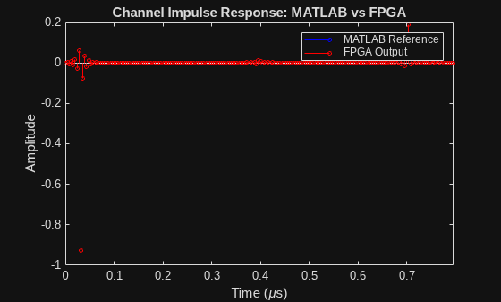
Validate the FPGA channel filter by transmitting an impulse and comparing the hardware output against the expected response from the comm.ChannelFilter System object.
Create an impulse signal. Place the delta function at an offset that accounts for the maximum integer path delay plus a margin.
impulseOffset = max(double(sl_in.PathIntegerDelays)) + 50;
impulseLen = sl_in.FrmLen;
impulse = zeros(impulseLen, 1);
impulse(impulseOffset + 1) = complex(fi(1 - 2^-15, 1, 16, 15), fi(0, 1, 16, 15));
Transmit the impulse continuously and capture the DUT output. Allow the transmit signal to propagate through the DUT before capturing. Convert the captured data to the channel emulator output data format of 16-bit signed integer with 13 fractional bits.
txData = int16(impulse * 2^15);
captureLen = impulseLen * 5;

transmit(device, txData, "continuous");
device(captureLen);
[dataOut, numSamps] = capture(device, captureLen);
dataOut = double(reinterpretcast(fi(dataOut, 1, 16, 0), numerictype(1, 16, 13)));
Compute the expected impulse response using the comm.ChannelFilter System object with the same channel parameters.
chanFilter = comm.ChannelFilter( ...
    SampleRate=sl_in.SampleRate, ...
    PathDelays=sl_in.PathDelays, ...
    NormalizeChannelOutputs=false, ...
    FilterDelaySource="Custom", ...
    FilterDelay=sl_in.FracFilterLen/2 - 1);
yGolden = chanFilter(impulse, sl_in.CIR(1,:));
Align the hardware output with the expected response using cross-correlation.
[xc, lags] = xcorr(dataOut, yGolden);
[~, maxIdx] = max(abs(xc));
offset = lags(maxIdx);

startIdx = max(1, offset + 1);
endIdx = min(numSamps, startIdx + length(yGolden) - 1);
alignedHw = dataOut(startIdx:endIdx);
alignedRef = yGolden(1:length(alignedHw));
Plot the FPGA impulse response against the MATLAB reference.
nShow = 200;
t_us = (0:nShow-1) / sl_in.SampleRate * 1e6;

figure;
stem(t_us, real(alignedRef(impulseOffset:impulseOffset+nShow-1)), 'b', 'MarkerSize', 3);
hold on
stem(t_us, real(alignedHw(impulseOffset:impulseOffset+nShow-1)), 'r', 'MarkerSize', 3);
xlabel('Time (\mus)'); ylabel('Amplitude');
title('Channel Impulse Response: MATLAB vs FPGA');
legend('MATLAB Reference', 'FPGA Output', 'Location', 'northeast');
xlim([0 t_us(end)]);
Verify Channel Frequency Response
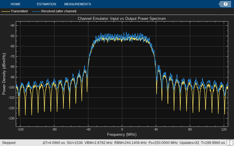
Transmit a wideband signal through the channel emulator and compare the input and output power spectra. Verify that frequency-selective fading from the 11-path channel is visible as spectral shaping on the output.
Generate a wideband test signal using random QPSK symbols with square-root raised cosine pulse shaping.
FrmLen = 50000;
sps = 4;
rolloff = 0.25;

numSyms = ceil(FrmLen / sps) + 10;
txSyms = qammod(randi([0 3], numSyms, 1), 4, UnitAveragePower=true);
txFilter = comm.RaisedCosineTransmitFilter( ...
    RolloffFactor=rolloff, ...
    FilterSpanInSymbols=8, ...
    OutputSamplesPerSymbol=sps);
txFiltered = txFilter(txSyms);
txShaped = txFiltered(1:FrmLen);
txShaped = txShaped / max(abs(txShaped)) * (1 - 2^-15);
txWideband = int16(txShaped * 2^15);
Transmit the wideband signal and capture the DUT output. Allow the transmit signal to propagate through the DUT before capturing. Convert the captured data to the channel emulator output data format of 16-bit signed integer with 13 fractional bits.
transmit(device, txWideband, "continuous");
device(FrmLen);
[rxData, nSamps] = capture(device, FrmLen);
rxData = double(reinterpretcast(fi(rxData, 1, 16, 0), numerictype(1, 16, 13)));
Compute and plot the power spectral density of the transmitted and received signals to view the effect of the channel.
sa = spectrumAnalyzer( ...
    SampleRate=sl_in.SampleRate, ...
    NumInputPorts=2, ...
    SpectrumType="Power density", ...
    Method="Welch", ...
    ChannelNames={'Transmitted', 'Received (after channel)'}, ...
    Title="Channel Emulator: Input vs Output Power Spectrum", ...
    ShowLegend=true);
nAnalyze = min(FrmLen, nSamps);
sa(txShaped(1:nAnalyze), rxData(1:nAnalyze));
release(sa);
Release Hardware Resources
Release the hardware resources.
release(dut);
release(device);
Next Steps
Because the path gains and delays are programmed at run time, you can adapt the channel emulator for other channel modeling scenarios without modifying the design or regenerating the bitstream. For example, you can:
Emulate time-varying fading conditions by updating the path gains periodically during transmission. Use the host interface script to reprogram the path gains stream while the channel emulator is running.
Customize the ray tracing scenario by changing the propagation environment, transmitter and receiver positions, or materials to generate path delays and gains that match your test conditions.
Emulate different channel models by writing path gains and delays from other MATLAB channel objects to the FPGA. For example, use the 5G Toolbox™
nrCDLChannel(5G Toolbox) ornrTDLChannel(5G Toolbox) fading channel models.

