comm.MIMOChannel
Filter input signal through MIMO multipath fading channel
Description
The comm.MIMOChannel
System object™ filters an input signal through a multiple-input/multiple-output (MIMO)
multipath fading channel. This object models Rayleigh and Rician fading and represents
the spatial correlation between the links by using the Kronecker model. The channel
filter applies a delay to the input, reflecting the delay of a particular path of the
overall channel. For processing details, see the Algorithms
section.
To filter an input signal through a MIMO multipath fading channel:
Create the
comm.MIMOChannelobject and set its properties.Call the object with arguments, as if it were a function.
To learn more about how System objects work, see What Are System Objects?
Creation
Description
mimochannel = comm.MIMOChannel
mimochannel = comm.MIMOChannel(Name=Value)comm.MIMOChannel(SampleRate=2) sets the input signal
sample rate to 2.
Properties
Usage
Syntax
Description
Y = mimochannel(X)X through the MIMO fading
channel and returns the result in Y.
To enable this syntax, set the ChannelFiltering property to true.
Y = mimochannel(X,seltx)seltx.
To enable this syntax set the AntennaSelection property to 'Tx'.
For example, this code shows how to select the first and third transmit antenna index as active.
mimochannel = comm.MIMOChannel('AntennaSelection','Tx');
seltx = [1 0 1];
...
y = mimochannel(x,seltx);
Y = mimochannel(X,selrx)selrx.
To enable this syntax set the AntennaSelection property to 'Rx'.
For example, this code shows how to select the second receive antenna index as active.
mimochannel = comm.MIMOChannel('AntennaSelection','Rx');
selrx = [0 1];
...
y = mimochannel(x,selrx);
Y = mimochannel(X,seltx,selrx)seltx and
selrx.
To enable this syntax set the AntennaSelection property to 'Tx and
Rx'.
For example, this code shows how to select the first and second transmit antenna and the second receive antenna as active.
mimochannel = comm.MIMOChannel( ...
    'AntennaSelection','Tx and Rx');
seltx = [1 1];
selrx = [0 1];
...
y = mimochannel(x,selrx);Y = mimochannel(___,inittime)
To enable this syntax, also set the FadingTechnique property to 'Sum of
sinusoids' and the InitialTimeSource property to 'Input
port'.
pathgains = mimochannel()
To enable this syntax, set the ChannelFiltering property to
false.
pathgains = mimochannel(seltx)seltx.
To enable this syntax set ChannelFiltering property to false and
the AntennaSelection property to 'Tx'.
pathgains = mimochannel(selrx)selrx.
To enable this syntax set the ChannelFiltering property to false and
the AntennaSelection property to 'Rx'.
pathgains = mimochannel(seltx,selrx)seltx and
selrx.
To enable this syntax set the ChannelFiltering property to false and
the AntennaSelection property to 'Tx and
Rx'.
pathgains = mimochannel(___,inittime)
To enable this syntax, also set the FadingTechnique property to 'Sum of
sinusoids' and the InitialTimeSource property to 'Input
port'.
Input Arguments
Output Arguments
Object Functions
To use an object function, specify the
System object as the first input argument. For
example, to release system resources of a System object named obj, use
this syntax:
release(obj)
Note
Examples
Create a 4-by-2 MIMO channel by using the MIMO channel System object. Modulate and spatially encode data, and then pass the data through the channel.
Generate QPSK-modulated data.
data = randi([0 3],1000,1);
modData = pskmod(data,4,pi/4);
Create an orthogonal space-time block encoder System object to encode the modulated data into four spatially separated streams. Then, encode the data.
ostbc = comm.OSTBCEncoder( ...
    'NumTransmitAntennas',4, ...
    'SymbolRate',1/2);
txSig = ostbc(modData);
Create a MIMO channel System object, using name-value pairs to set the properties. The channel consists of two paths, each with a maximum Doppler shift of 5 Hz. Set the SpatialCorrelationSpecification property to 'None', which requires that you specify the number of transmit and receive antennas. Specify four transmit antennas and two receive antennas.
mimochannel = comm.MIMOChannel( ...
    'SampleRate',1000, ...
    'PathDelays',[0 2e-3], ...
    'AveragePathGains',[0 -5], ...
    'MaximumDopplerShift',5, ...
    'SpatialCorrelationSpecification','None', ...
    'NumTransmitAntennas',4, ...
    'NumReceiveAntennas',2);
Pass the modulated and encoded signal through the MIMO channel.
rxSig = mimochannel(txSig);
Create a time vector, t, to use for plotting the power of the received signal.
ts = 1/mimochannel.SampleRate;
t = (0:ts:(size(txSig,1)-1)*ts)';
Calculate and plot the power of the signal received by antenna 1.
pwrdB = 20*log10(abs(rxSig(:,1)));
plot(t,pwrdB)
title('Channel Response Power (dBW)')
xlabel('Time (s)')
ylabel('Power (dBW)')

Produce the multipath MIMO fading channel response by using two different path gain sampling rates. The multipath MIMO fading channel System object allows you to set the path gain sampling rate equal to the signal sampling rate or a lower rate computed based on the configuration of the object.
Apply 32-QAM modulation to randomly generated data.
M = 32;
spf = 2^12;
insig = randi([0,M-1],spf,2);
channelInput = qammod(insig,M);
numFrames = 2e4;
Create a multipath MIMO fading channel System object with three paths. Before comparing the execution times, run once to load the object.
mimochan = comm.MIMOChannel( ...
    SampleRate=20e6, ...
    PathDelays=[0 1.5e-7 1.5e-7], ...
    AveragePathGains=[2 3 5], ...
    NormalizePathGains=true, ...
    MaximumDopplerShift=30, ...
    DopplerSpectrum= ...
        {doppler('Jakes'),doppler('Flat'),doppler('Bell')}, ...
    RandomStream='mt19937ar with seed', ...
    Seed=22, ...
    PathGainsOutputPort=true)
mimochan =
  comm.MIMOChannel with properties:

                         SampleRate: 20000000
                 PathGainSampleRate: 'signal'
                         PathDelays: [0 1.5000e-07 1.5000e-07]
                   AveragePathGains: [2 3 5]
                 NormalizePathGains: true
                 FadingDistribution: 'Rayleigh'
                MaximumDopplerShift: 30
                    DopplerSpectrum: {[1×1 struct]  [1×1 struct]  [1×1 struct]}
    SpatialCorrelationSpecification: 'Separate Tx Rx'
          TransmitCorrelationMatrix: [2×2 double]
           ReceiveCorrelationMatrix: [2×2 double]
                   AntennaSelection: 'Off'
            NormalizeChannelOutputs: true
                   ChannelFiltering: true
                PathGainsOutputPort: true

  Show all properties
mimochan(channelInput);
Use the info object function to show the configuration. Filter the modulated data by using the multipath MIMO fading channel System object. Show the time required to filter a number of frames of data with the path gain sampling rate equal to the signal sampling rate.
info(mimochan)
ans = struct with fields:
    ChannelFilterCoefficients: [3×4 double]
           ChannelFilterDelay: 0
          NumSamplesProcessed: 4096
           PathGainSampleRate: 20000000
tic
for ii = 1:numFrames
    [chanOut1,pathGains1] = mimochan(channelInput);
end
toc
Elapsed time is 11.075703 seconds.
Release the object and change the PathGainSampleRate to 'auto'. Use the info object function to show the configuration. Repeat the MIMO channel filtering of the modulated data and show the time required to filter the same number of frames of data with the lower path gain sampling rate computed by the object.
release(mimochan);
mimochan.PathGainSampleRate = 'auto'
mimochan =
comm.MIMOChannel with properties:
SampleRate: 20000000
PathGainSampleRate: 'auto'
PathDelays: [0 1.5000e-07 1.5000e-07]
AveragePathGains: [2 3 5]
NormalizePathGains: true
FadingDistribution: 'Rayleigh'
MaximumDopplerShift: 30
DopplerSpectrum: {[1×1 struct] [1×1 struct] [1×1 struct]}
SpatialCorrelationSpecification: 'Separate Tx Rx'
TransmitCorrelationMatrix: [2×2 double]
ReceiveCorrelationMatrix: [2×2 double]
AntennaSelection: 'Off'
NormalizeChannelOutputs: true
ChannelFiltering: true
PathGainsOutputPort: true
Show all properties
mimochan(channelInput);
info(mimochan)
ans = struct with fields:
    ChannelFilterCoefficients: [3×4 double]
           ChannelFilterDelay: 0
          NumSamplesProcessed: 4096
           PathGainSampleRate: 300.0030
tic
for ii = 1:numFrames
    [chanOut2,pathGains2] = mimochan(channelInput);
end
toc
Elapsed time is 4.952337 seconds.
Generate path gains for a 2-by-2 Rayleigh fading channel and examine the spatial correlation characteristics of the channel realization. Use the release object function to unlock the object to set the AntennaSelection property to 'Tx and Rx' and then confirm the unselected transmit-receive antenna pairs.
Create a 2-by-2 MIMO channel System object with two discrete paths and channel filtering disabled. Each path has different transmit and receive correlation matrices, specified by the TransmitCorrelationMatrix and ReceiveCorrelationMatrix properties.
mimoChan = comm.MIMOChannel( ...
    'SampleRate',1000, ...
    'PathDelays',[0 1e-3], ...
    'AveragePathGains',[3 5], ...
    'NormalizePathGains',false, ...
    'MaximumDopplerShift',5, ...
    'TransmitCorrelationMatrix',cat(3,eye(2),[1 0.1;0.1 1]), ...
    'ReceiveCorrelationMatrix',cat(3,[1 0.2;0.2 1],eye(2)), ...
    'RandomStream','mt19937ar with seed', ...
    'Seed',33, ...
    'ChannelFiltering',false);
Generate channel response path gains using the MIMO channel object.
pathGains = mimoChan();
The transmit spatial correlation for the first discrete path at the first receive antenna is specified as an identity matrix in the TransmitCorrelationMatrix property. Confirm that the channel output pathGains exhibits the same statistical characteristics by using the corrcoef function to display the transmit spatial correlation for the first discrete path and the first receive antenna.
corrcoef(squeeze(pathGains(:,1,:,1)))
ans = 2×2 complex

   1.0000 + 0.0000i  -0.3391 + 0.4285i
  -0.3391 - 0.4285i   1.0000 + 0.0000i
The transmit spatial correlation for the second discrete path at the second receive antenna is specified as [1 0.1;0.1 1] in the TransmitCorrelationMatrix property. Confirm that the channel output pathGains exhibits the same statistical characteristics by using the corrcoef function to display the transmit spatial correlation for the second discrete path and the second receive antenna.
corrcoef(squeeze(pathGains(:,2,:,2)))
ans = 2×2 complex

   1.0000 + 0.0000i  -0.8989 - 0.2663i
  -0.8989 + 0.2663i   1.0000 + 0.0000i
The receive spatial correlation for the first discrete path at the second transmit antenna is specified as [1 0.2;0.2 1] in the ReceiveCorrelationMatrix property. Confirm that the channel output pathGains exhibits the same statistical characteristics by using the corrcoef function to display the receive spatial correlation for the first discrete path and the second transmit antenna.
corrcoef(squeeze(pathGains(:,1,2,:)))
ans = 2×2 complex

   1.0000 + 0.0000i   0.9170 + 0.3141i
   0.9170 - 0.3141i   1.0000 + 0.0000i
The receive spatial correlation for the second discrete path at the first transmit antenna is specified as an identity matrix in the ReceiveCorrelationMatrix property. Confirm that the channel output pathGains exhibits the same statistical characteristics by using the corrcoef function to display the receive spatial correlation for the second discrete path and the first transmit antenna.
corrcoef(squeeze(pathGains(:,2,1,:)))
ans = 2×2 complex

   1.0000 + 0.0000i   0.9227 - 0.3435i
   0.9227 + 0.3435i   1.0000 + 0.0000i
Create a frequency-selective MIMO channel, and then display its impulse and frequency responses.
Set the sample rate to 10 MHz. Specify path delays and gains using the extended vehicular A (EVA) channel parameters. Set the maximum Doppler shift to 70 Hz.
fs = 10e6;                                                % Hz
pathDelays = [0 30 150 310 370 710 1090 1730 2510]*1e-9;  % Seconds
avgPathGains = [0 -1.5 -1.4 -3.6 -0.6 -9.1 -7 -12 -16.9]; % dB
fD = 70;                                                  % Hz
Create a 2-by-2 MIMO channel System object, specifying the previously defined parameters and setting channel visualization to plot the impulse and frequency responses. By default, the plot displays the antenna pair corresponding to first transmit and receive antennas.
mimoChan = comm.MIMOChannel(SampleRate=fs, ...
    PathDelays=pathDelays, ...
    AveragePathGains=avgPathGains, ...
    MaximumDopplerShift=fD, ...
    Visualization='Impulse and frequency responses');
Generate random binary data, and then pass it through the MIMO channel. The impulse response plot enables you to easily identify the individual paths and their corresponding filter coefficients. The frequency response plot shows the frequency-selective nature of the EVA channel.
x = randi([0 1],1000,2);
y = mimoChan(x);


To view the antenna pair corresponding to the second transmit and first receive antennas, release the MIMO channel System object, and then set its AntennaPairsToDisplay property to [2 1]. Because the AntennaPairsToDisplay property is nontunable, to change its value, you must release the System object.
release(mimoChan)
mimoChan.AntennaPairsToDisplay = [2 1];
y = mimoChan(x);


Create and visualize the Doppler spectra of a MIMO channel that has two paths.
Construct a cell array of Doppler structures to be used in creating the channel. Set the Doppler spectrum of the first path to be bell shaped and the second path to be flat.
dp{1} = doppler('Bell');
dp{2} = doppler('Flat');
Create a 2-by-2 MIMO channel System object, specifying two paths and a maximum Doppler shift of 100 Hz, disabling the channel filtering, and enabling the visualization of the Doppler spectrum for the first Doppler path.
mimoChan = comm.MIMOChannel(SampleRate=1000, ...
    PathDelays=[0 0.002], ...
    AveragePathGains=[0 -3], ...
    MaximumDopplerShift=100, ...
    DopplerSpectrum=dp, ...
    ChannelFiltering=false, ...
    NumSamples=10000, ...
    Visualization='Doppler spectrum', ...
    PathsForDopplerDisplay=1);
Use the MIMO channel to generate the Doppler spectrum of the first path. Because the Doppler spectrum plot does not update until its buffer is filled, call the MIMO channel object multiple times to help improve the accuracy of the estimate. Observe that the spectrum has a bell shape and that its minimum and maximum frequencies fall within the limits set by the MaximumDopplerShift property.
for k = 1:25
    mimoChan();
end

Release the MIMO channel object, and set its PathsForDopplerDisplay property to display the second path. Because the PathsForDopplerDisplay property is nontunable, to change its value, you must release the System object. Call the object multiple times to display the Doppler spectrum of the second path. The results show that the spectrum is flat.
release(mimoChan)
mimoChan.PathsForDopplerDisplay = 2;
for k = 1:25
    y = mimoChan();
end

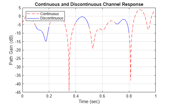
Show that the channel state is maintained for discontinuous transmissions by using MIMO channel System objects configured to use the sum-of-sinusoids fading technique. Observe discontinuous channel response segments overlaid on a continuous channel response.
Set the channel properties.
fs = 1000;               % Sample rate (Hz)
pathDelays = [0 2.5e-3]; % Path delays (s)
pathPower = [0 -6];      % Path power (dB)
fD = 5;                  % Maximum Doppler shift (Hz)
ns = 1000;               % Number of samples
nsdel = 100;             % Number of samples for delayed paths
Define a continuous time span and three discontinuous time segments over which to plot and view the channel response. View a 1000-sample continuous channel response starting at time 0 and three 100-sample channel responses starting at times 0.1, 0.4, and 0.7 seconds, respectively.
to0 = 0.0;
to1 = 0.1;
to2 = 0.4;
to3 = 0.7;
t0 = (to0:ns-1)/fs;      % Transmission 0
t1 = to1+(0:nsdel-1)/fs; % Transmission 1
t2 = to2+(0:nsdel-1)/fs; % Transmission 2
t3 = to3+(0:nsdel-1)/fs; % Transmission 3
Create a flat-fading 2-by-2 MIMO channel System object, disabling channel filtering and specifying a 1000 Hz sampling rate, the sum-of-sinusoids fading technique, and the number of samples to view. Specify a seed value so that results can be repeated. Use the default InitialTime property setting so that the fading channel is simulated from time 0.
mimoChan1 = comm.MIMOChannel('SampleRate',fs, ...
    'MaximumDopplerShift',fD, ...
    'RandomStream','mt19937ar with seed', ...
    'Seed',17, ...
    'FadingTechnique','Sum of sinusoids', ...
    'ChannelFiltering',false, ...
    'NumSamples',ns);
Create a clone of the MIMO channel System object. Change the number of samples for the delayed paths and the source for the initial time so that you can specify the fading channel offset time as an input argument when calling the System object.
mimoChan2 = clone(mimoChan1);
mimoChan2.InitialTimeSource = 'Input port';
mimoChan2.NumSamples = nsdel;
Save the path gain output for the continuous channel response by using the mimoChan1 object and for the discontinuous delayed channel responses by using the mimoChan2 object with initial time offsets provided as input arguments.
pg0 = mimoChan1();
pg1 = mimoChan2(to1);
pg2 = mimoChan2(to2);
pg3 = mimoChan2(to3);
Compare the number of samples processed by the two channels by using the info method. The results show that mimoChan1 processed 1000 samples and that mimoChan2 processed only 300 samples.
G = info(mimoChan1);
H = info(mimoChan2);
[G.NumSamplesProcessed H.NumSamplesProcessed]
ans = 1×2

        1000         300
Convert the path gains into decibels for the path corresponding to the first transmit and first receive antenna.
pathGain0 = 20*log10(abs(pg0(:,1,1,1)));
pathGain1 = 20*log10(abs(pg1(:,1,1,1)));
pathGain2 = 20*log10(abs(pg2(:,1,1,1)));
pathGain3 = 20*log10(abs(pg3(:,1,1,1)));
Plot the path gains for the continuous and discontinuous cases. The results show that the gains for the three segments match the gain for the continuous case. The alignment of the two shows that the sum-of-sinusoids technique is ideally suited to the simulation of packetized data because the channel characteristics are maintained even when data is not transmitted.
plot(t0,pathGain0,'r--')
hold on
plot(t1,pathGain1,'b')
plot(t2,pathGain2,'b')
plot(t3,pathGain3,'b')
grid
title('Continuous and Discontinuous Channel Response')
xlabel('Time (sec)')
ylabel('Path Gain (dB)')
legend('Continuous','Discontinuous','location','nw')
Demonstrate the advantage of using the sum-of-sinusoids fading technique when simulating a channel with burst data.
Set the simulation parameters such that the sampling rate is 100 kHz, the total simulation time is 100 seconds, and the duty cycle for the burst data is 25%.
fs = 1e5;   % Hz
tsim = 100; % seconds
dutyCycle = 0.25;
Create a flat-fading 2-by-2 MIMO channel System object, specifying the sample rate and using the default filtered Gaussian noise technique.
fgn = comm.MIMOChannel('SampleRate',fs);Create a similar MIMO channel System object, specifying the same sample rate as the previous MIMO channel object but using the sum-of-sinusoids technique. Additionally specify 48 sinusoids and for the fading process start times to be given as an input argument.
sos = comm.MIMOChannel('SampleRate',fs, ...
    'FadingTechnique','Sum of sinusoids', ...
    'NumSinusoids',48, ...
    'InitialTimeSource','Input port');
Run a continuous sequence of random bits through the filtered Gaussian noise MIMO channel object. Use the tic and toc stopwatch timer functions to measure the execution time of the System object call.
tic
y = fgn(randi([0 1],fs*tsim,2));
tFGN = toc;
To transmit a data burst each second, pass random bits through the sum-of-sinusoids MIMO channel object by calling it inside of a for loop. Use the tic and toc stopwatch timer functions to measure the execution time.
tic
for k = 1:tsim
    z = sos(randi([0 1],fs*dutyCycle,2),0.5+(k-1));
end
tSOS = toc;
Compare the ratio of the sum-of-sinusoids execution time to the filtered Gaussian noise execution time. The ratio is less than one, which indicates that the sum-of-sinusoids technique is faster than the filtered Gaussian noise technique.
tSOS/tFGN
ans =
0.2871
Using one MIMO channel System object™ and two identically configured channel filter System objects, switch a link-level simulation between 3-by-2 downlink and reciprocal 2-by-3 uplink signal transmissions.
Define system parameters.
modOrder = 256;        % Modulation order
Nant1 = 3;             % Number of 'transmit' antennas
Nant2 = 2;             % Number of 'receive' antennas
Rs = 1e6;              % Sample rate
pd = [0 1.5 2.3]*1e-6; % Path delays
frmLen = 1e3;          % Frame length
Create a MIMO channel System object™, configuring it for path gain generation by disabling channel filtering.
chan = comm.MIMOChannel( ...
    'SampleRate',Rs, ...
    'PathDelays',pd, ...
    'AveragePathGains',[1.5 1.2 0.2], ...
    'MaximumDopplerShift',300, ...
    'SpatialCorrelationSpecification','none', ...
    'NumTransmitAntennas',Nant1, ...
    'NumReceiveAntennas',Nant2, ...
    'ChannelFiltering',false, ...
    'NumSamples',frmLen);
Create identical channel filter System objects for both transmission directions: one channel filter for the Nant1-by-Nant2 downlink channel (3 transmit antennas to 2 receive antennas) and a reciprocal channel filter for the Nant2-by-Nant1 uplink channel (2 transmit antennas to 3 receive antennas).
chanFiltDownlink = comm.ChannelFilter( ...
    'SampleRate',Rs, ...
    'PathDelays',pd);
chanFiltUplink = clone(chanFiltDownlink);
Downlink Transmission
Generate random path gains for one frame of the downlink 3-by-2 channel. Pass randomly generated 256-QAM signals through the 3-by-2 downlink channel.
pgDownlink = chan();
x = qammod(randi([0 modOrder-1],frmLen,Nant1),modOrder);
yDL = chanFiltDownlink(x,pgDownlink);
Uplink Transmission
Switch the link direction. Run the channel object to generate another frame of path gains, permuting its 3rd (Tx) and 4th (Rx) dimensions for the reciprocal uplink 2-by-3 channel. Pass randomly generated 256-QAM signals through the 2-by-3 reciprocal uplink channel.
pgUplink = permute(chan(),[1 2 4 3]);
x = qammod(randi([0 modOrder-1],frmLen,Nant2),modOrder);
yUL = chanFiltUplink(x,pgUplink);
Downlink and Uplink Array Dimensions
Show the sizes of the downlink and uplink path gain arrays returned by the MIMI channel object as an -by--by--by- array.
is the number of samples.
is the number of path delays.
is the number of transmit antennas.
Nant1for downlink andNant2for uplink.is the number of receive antennas.
Nant2for downlink andNant1for uplink.
size(pgDownlink)
ans = 1×4

        1000           3           3           2
size(pgUplink)
ans = 1×4

        1000           3           2           3
Show the size of the channel output matrices returned by the MIMI channel object as an -by- matrix. is the number of samples. is the number of receive antennas.
size(yDL)
ans = 1×2

        1000           2
size(yUL)
ans = 1×2

        1000           3
The default value of the PathGainsSampleRate property ('signal') computes a path gain value for each sample of the input signal. In practice, the wireless channel does not change that often. Setting PathGainsSampleRate property to 'auto' allows more infrequent path gain computations, at a rate that is faster than the channel variation rate (10*MaximumDopplerShift) and evenly divides the sample rate of the input signal. As a result, the channel computation takes less time.
To illustrate this scenario, consider a multi path channel that changes as per a 200 Hz Doppler. A signal sampled at 10 MHz is passed to the channel.
Fs = 10e6;          % 10 MHz
MaxD = 200;         % Max Doppler shift (Hz)
pd = (0:5:15)*1e-6; % Discrete delays of four-path channel (s)
pg = [0 -3 -6 -9];  % Average path gains (dB)
Construct two different MIMO channels. In the first MIMO channel, set PathGainSampleRate to 'signal'. In the second, set PathGainSampleRate to 'auto'.
chanSignal = comm.MIMOChannel( ...
    SampleRate=Fs, ...
    PathDelays=pd, ...
    AveragePathGains=pg, ...
    MaximumDopplerShift=MaxD, ...
    RandomStream="mt19937ar with seed");
chanAuto = clone(chanSignal);
chanAuto.PathGainSampleRate = 'auto';
Compare the actual path gain rates, using the info method.
infoSig = info(chanSignal);
infoAuto = info(chanAuto);
fprintf('Path gain sample rate for ''signal'': %d Hz\n', infoSig.PathGainSampleRate)
Path gain sample rate for 'signal': 10000000 Hz
fprintf('Path gain sample rate for ''auto'': %d Hz\n', infoAuto.PathGainSampleRate)Path gain sample rate for 'auto': 2000 Hz
Next, construct a series of QPSK signals and pass them through the two MIMO channels.
M = 4;               % QPSK modulation
phaseoffset = pi/4;  % Phase offset
bitsPerFrame = 1000;
numFrames = 5000;
[tsig, tauto] = deal(0);
tic;
for i = 1:numFrames
    msg = randi([0 1], bitsPerFrame, 2);
    modSignal = pskmod(msg,M,phaseoffset,InputType='bit');
    % First, measure time spent with PathGainSampleRate = 'signal'
    tic;
    chanSignal(modSignal);
    tsig = tsig + toc;
    % Second, measure time spent with PathGainSampleRate = 'auto'
    tic;
    chanAuto(modSignal);
    tauto = tauto + toc;
end
Compare the computation times of the two channels.
fprintf('Duration for ''signal'': %.1f sec\n', tsig)Duration for 'signal': 1.1 sec
fprintf('Duration for ''auto'': %.1f sec\n', tauto)Duration for 'auto': 0.5 sec
More About
Algorithms
References
[1] Oestges, Claude, and Bruno Clerckx., MIMO Wireless Communications: From Real-World Propagation to Space-Time Code Design. 1st ed. Boston, MA: Elsevier, 2007.
[2] Correia, Luis M., and European Cooperation in the Field of Scientific and Technical Research (Organization), eds. Mobile Broadband Multimedia Networks: Techniques, Models and Tools for 4G. 1st ed. Amsterdam; Boston: Elsevier/Academic Press, 2006.
[3] Kermoal, J.P., L. Schumacher, K.I. Pedersen, P.E. Mogensen, and F. Frederiksen. “A Stochastic MIMO Radio Channel Model with Experimental Validation.” IEEE® Journal on Selected Areas in Communications 20, no. 6 (August 2002): 1211–26. https://doi.org/10.1109/JSAC.2002.801223.
[4] Jeruchim, Michel C., Philip Balaban, and K. Sam Shanmugan. Simulation of Communication Systems. Second edition. Boston, MA: Springer US, 2000.
[5] Patzold, M., Cheng-Xiang Wang, and B. Hogstad. “Two New Sum-of-Sinusoids-Based Methods for the Efficient Generation of Multiple Uncorrelated Rayleigh Fading Waveforms.” IEEE Transactions on Wireless Communications 8, no. 6 (June 2009): 3122–31. https://doi.org/10.1109/TWC.2009.080769.
Extended Capabilities
Version History
Introduced in R2012aSee Also
Objects
comm.AWGNChannel|comm.RayleighChannel|comm.RicianChannel|comm.RayTracingChannel|comm.ChannelFilter