Driving Scenario Designer
Design driving scenarios, configure sensors, and generate synthetic data
Description
The Driving Scenario Designer app enables you to design synthetic driving scenarios for testing your autonomous driving systems.
Using the app, you can:
Create road and actor models using a drag-and-drop interface.
Configure vision, radar, lidar, INS, and ultrasonic sensors mounted on the ego vehicle. You can use these sensors to generate actor and lane boundary detections, point cloud data, and inertial measurements.
Load driving scenarios representing European New Car Assessment Programme (Euro NCAP®) test protocols [1][2][3] and other prebuilt scenarios.
Import ASAM OpenDRIVE® roads and lanes into a driving scenario. The app supports OpenDRIVE® file versions 1.4 and 1.5, as well as ASAM OpenDRIVE file version 1.6.
Import road data from OpenStreetMap®, HERE HD Live Map 1 , or Zenrin Japan Map API 3.0 (Itsumo NAVI API 3.0) 2 web services into a driving scenario.
Importing data from the Zenrin Japan Map API 3.0 (Itsumo NAVI API 3.0) service requires Automated Driving Toolbox Importer for Zenrin Japan Map API 3.0 (Itsumo NAVI API 3.0) Service.
Export the road network in a driving scenario to the ASAM OpenDRIVE file format. The app supports OpenDRIVE file versions 1.4 and 1.5, as well as ASAM OpenDRIVE file version 1.6.
Export road network, actors, and trajectories in a driving scenario to the ASAM OpenSCENARIO® 1.0 file format.
Export road network and static actors to the RoadRunner HD Map file format.
Open the RoadRunner application with automatic import of the current scene and scenario elements.
Export synthetic sensor detections to MATLAB®.
Generate MATLAB code of the scenario and sensors, and then programmatically modify the scenario and import it back into the app for further simulation.
Generate a Simulink® model from the scenario and sensors, and use the generated models to test your sensor fusion or vehicle control algorithms.
To learn more about the app, see these videos:

Open the Driving Scenario Designer App
MATLAB Toolstrip: On the Apps tab, under Automotive, click the app icon.
MATLAB command prompt: Enter
drivingScenarioDesigner.
Examples
Create a driving scenario of a vehicle driving down a curved road, and export the road and vehicle models to the MATLAB workspace. For a more detailed example of creating a driving scenario, see Create Driving Scenario Interactively and Generate Synthetic Sensor Data.
Open the Driving Scenario Designer app.
drivingScenarioDesigner
Create a curved road. On the app toolstrip, click Add Road. Click the bottom of the canvas, extend the road path to the middle of the canvas, and click the canvas again. Extend the road path to the top of the canvas, and then double-click to create the road. To make the curve more complex, click and drag the road centers (open circles), double-click the road to add more road centers, or double-click an entry in the heading (°) column of the Road Centers table to specify a heading angle as a constraint to a road center point.

Add lanes to the road. In the left pane, on the Roads
tab, expand the Lanes section. Set Number of
Lanes to 2. By default, the road is
one-way and has solid lane markings on either side to indicate the
shoulder.
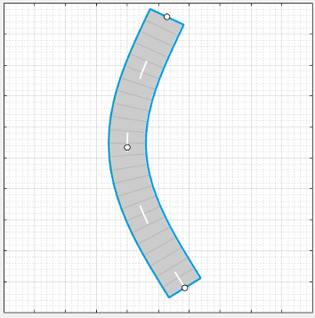
Add a vehicle at one end of the road. On the app toolstrip, select Add Actor > Car. Then click the road to set the initial position of the car.
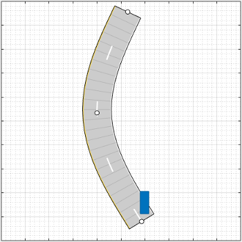
Set the driving trajectory of the car. Right-click the car, select Add Forward Waypoints, and add waypoints for the car to pass through. After you add the last waypoint, press Enter. The car autorotates in the direction of the first waypoint.

Adjust the speed of the car as it passes between waypoints. In the
Waypoints, Speeds, Wait Times, and Yaw table in the
left pane, set the velocity, v (m/s), of the ego
vehicle as it enters each waypoint segment. Increase the speed of the car
for the straight segments and decrease its speed for the curved segments.
For example, the trajectory has six waypoints, set the v
(m/s) cells to 30, 20,
15, 15, 20, and
30.

Run the scenario, and adjust settings as needed. Then click Save > Roads & Actors to save the road and car models to a MAT file.
Generate lidar point cloud data from a prebuilt Euro NCAP driving scenario.
For more details on prebuilt scenarios available from the app, see Prebuilt Driving Scenarios in Driving Scenario Designer.
For more details on available Euro NCAP scenarios, see Euro NCAP Driving Scenarios in Driving Scenario Designer.
Load a Euro NCAP autonomous emergency braking (AEB) scenario of a collision with a pedestrian child. At collision time, the point of impact occurs 50% of the way across the width of the car.
path = fullfile(matlabroot,'toolbox','shared','drivingscenario', ...
    'PrebuiltScenarios','EuroNCAP');
addpath(genpath(path)) % Add folder to path
drivingScenarioDesigner('AEB_PedestrianChild_Nearside_50width.mat')
rmpath(path) % Remove folder from path
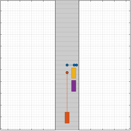
Add a lidar sensor to the ego vehicle. First click Add Lidar. Then, on the Sensor Canvas, click the predefined sensor location at the roof center of the car. The lidar sensor appears in black at the predefined location. The gray color that surrounds the car is the coverage area of the sensor.
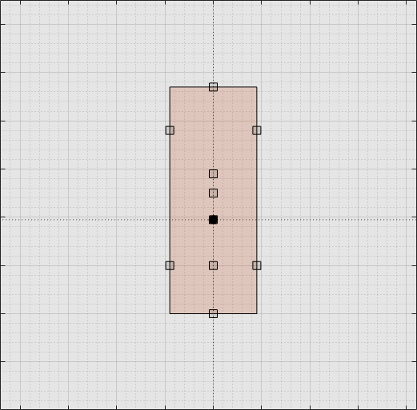
Run the scenario. Inspect different aspects of the scenario by toggling between canvases and views. You can toggle between the Sensor Canvas and Scenario Canvas and between the Bird's-Eye Plot and Ego-Centric View.
In the Bird's-Eye Plot and Ego-Centric View, the actors are displayed as meshes instead of as cuboids. To change the display settings, use the Display options on the app toolstrip.

Export the sensor data to the MATLAB workspace. Click Export > Export Sensor Data, enter a workspace variable name, and click OK.
Programmatically create a driving scenario, radar sensor, and camera sensor. Then import the scenario and sensors into the app. For more details on working with programmatic driving scenarios and sensors, see Create Driving Scenario Variations Programmatically.
Create a simple driving scenario by using a drivingScenario object. In
this scenario, the ego vehicle travels straight on a 50-meter road segment
at a constant speed of 30 meters per second. For the ego vehicle, specify a
ClassID property of 1. This value
corresponds to the app Class ID of
1, which refers to actors of class
Car. For more details on how the app defines classes, see
the Class parameter description in the Actors
parameter tab.
scenario = drivingScenario;
roadCenters = [0 0 0; 50 0 0];
road(scenario,roadCenters);

egoVehicle = vehicle(scenario,'ClassID',1,'Position',[5 0 0]);
waypoints = [5 0 0; 45 0 0];
speed = 30;
smoothTrajectory(egoVehicle,waypoints,speed)
Create a radar sensor by using a drivingRadarDataGenerator object, and create a camera sensor
by using a visionDetectionGenerator
object. Place both sensors at the vehicle origin, with the radar facing
forward and the camera facing backward.
radar = drivingRadarDataGenerator('MountingLocation',[0 0 0]);
camera = visionDetectionGenerator('SensorLocation',[0 0],'Yaw',-180);
Import the scenario, front-facing radar sensor, and rear-facing camera sensor into the app.
drivingScenarioDesigner(scenario,{radar,camera})

You can then run the scenario and modify the scenario and sensors. To
generate new drivingScenario,
drivingRadarDataGenerator, and
visionDetectionGenerator objects, on the app toolstrip,
select Export > Export MATLAB Function, and then run the generated function.
Load a driving scenario containing a sensor and generate a Simulink model from the scenario and sensor. For a more detailed example on generating Simulink models from the app, see Generate Sensor Blocks Using Driving Scenario Designer.
Load a prebuilt driving scenario into the app. The scenario contains two vehicles crossing through an intersection. The ego vehicle travels north and contains a camera sensor. This sensor is configured to detect both objects and lanes.
path = fullfile(matlabroot,'toolbox','shared','drivingscenario','PrebuiltScenarios');
addpath(genpath(path)) % Add folder to path
drivingScenarioDesigner('EgoVehicleGoesStraight_VehicleFromLeftGoesStraight.mat')
rmpath(path) % Remove folder from path
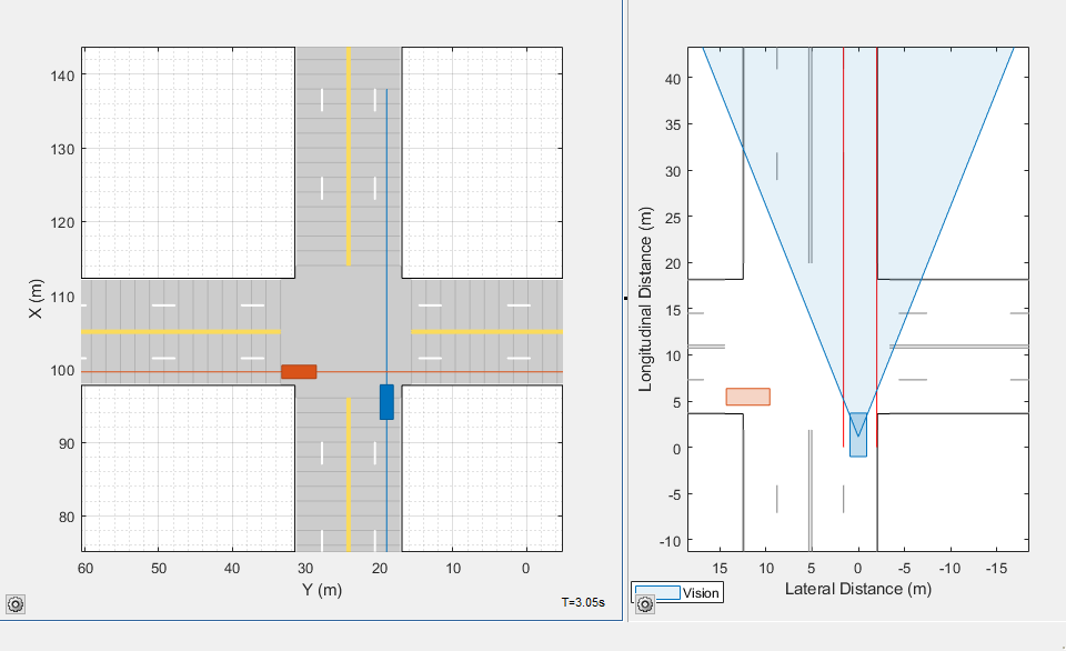
Generate a Simulink model of the scenario and sensor. On the app toolstrip, select Export > Export Simulink Model. If you are prompted, save the scenario file.

The Scenario Reader block reads the road and actors from the scenario file. To update the scenario data in the model, update the scenario in the app and save the file.
The Vision Detection Generator block recreates the camera sensor defined in the app. To update the sensor in the model, update the sensor in the app, select Export > Export Sensor Simulink Model, and copy the newly generated sensor block into the model. If you updated any roads or actors while updating the sensors, then select Export > Export Simulink Model. In this case, the Scenario Reader block accurately reads the actor profile data and passes it to the sensor.
Create a scenario with vehicle trajectories that you can later recreate in Simulink for simulation in a 3D environment.
Open one of the prebuilt scenarios that recreates a default scene
available through the 3D environment. On the app toolstrip, select Open > Prebuilt Scenario > Simulation3D and select a scenario. For example, select the
DoubleLaneChange.mat scenario.
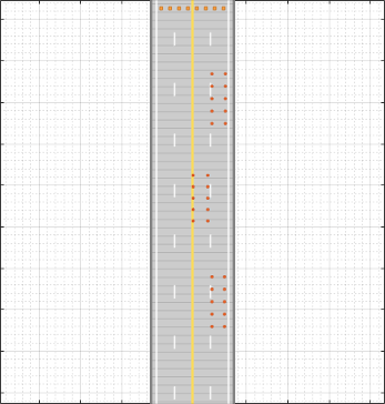
Specify a vehicle and its trajectory.
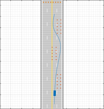
Update the dimensions of the vehicle to match the dimensions of the predefined vehicle types in the 3D simulation environment.
On the Actors tab, select the 3D Display Type option you want.
On the app toolstrip, select 3D Display > Use 3D Simulation Actor Dimensions. In the Scenario Canvas, the actor dimensions update to match the predefined dimensions of the actors in the 3D simulation environment.
Preview how the scenario will look when you later recreate it in Simulink. On the app toolstrip, select 3D Display > View Simulation in 3D Display. After the 3D display window opens, click Run.
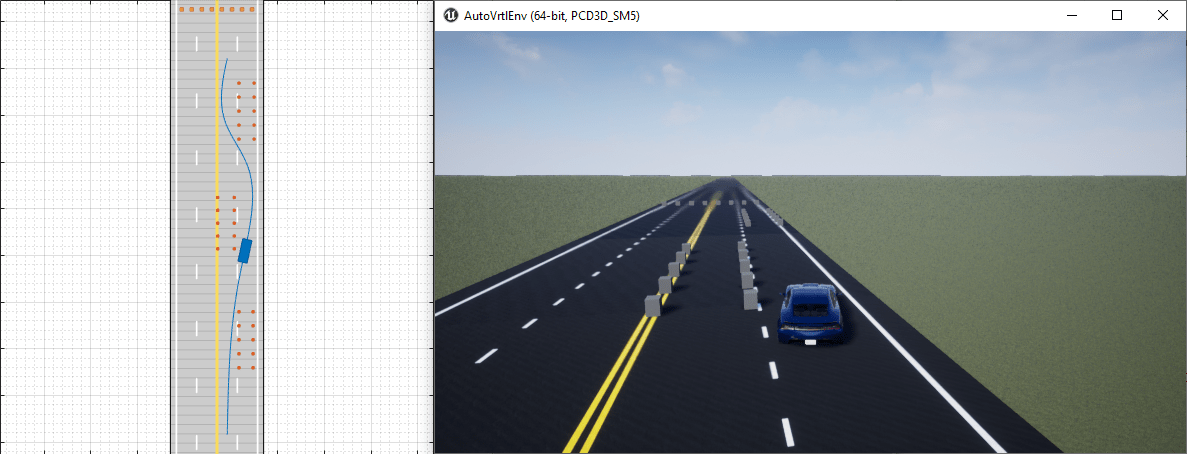
Modify the vehicle and trajectory as needed. Avoid changing the road network or the actors that were predefined in the scenario. Otherwise, the app scenario will not match the scenario that you later recreate in Simulink. If you change the scenario, the 3D display window closes.
When you are done modifying the scenario, you can recreate it in a Simulink model for use in the 3D simulation environment. For an example that shows how to set up such a model, see Visualize Sensor Data from Unreal Engine Simulation Environment.
Related Examples
- Create Driving Scenario Interactively and Generate Synthetic Sensor Data
- Create Roads with Multiple Lane Specifications Using Driving Scenario Designer
- Generate INS Sensor Measurements from Interactive Driving Scenario
- Create Reverse Motion Driving Scenarios Interactively
- Import ASAM OpenDRIVE Roads into Driving Scenario
- Import HERE HD Live Map Roads into Driving Scenario
- Import OpenStreetMap Data into Driving Scenario
- Import Zenrin Japan Map API 3.0 (Itsumo NAVI API 3.0) into Driving Scenario
- Generate Sensor Blocks Using Driving Scenario Designer
- Export Driving Scenario to RoadRunner Scenario Simulation
Parameters
To enable the Roads parameters, add at least one road to the scenario. Then, select a road from either the Scenario Canvas or the Road parameter. The parameter values in the Roads tab are based on the road you select.
| Parameter | Description |
|---|---|
| Road | Road to modify, specified as a list of the roads in the scenario. |
| Name | Name of the road. The name of an imported road depends on the map service. For example, when you generate a road using OpenStreetMap data, the app uses the name of the road when it is available. Otherwise, the app uses the road ID specified by the OpenStreetMap data. |
| Width (m) | Width of the road, in meters, specified as a decimal scalar in the range (0, 50]. If the curvature of the road is too sharp to accommodate the specified road width, the app does not generate the road. Default:
|
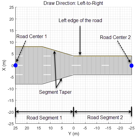
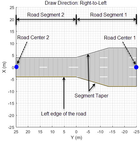
| Number of Road Segments | Number of road segments, specified as a positive integer. Use this parameter to enable composite lane specification by dividing the road into road segments. Each road segment represents a part of the road with a distinct lane specification. Lane specifications differ from one road segment to another. For more information on composite lane specifications, see Composite Lane Specification. Default: |
| Segment Range | Normalized range for each road segment, specified
as a row vector of values in the range (0, 1). The
length of the vector must be equal to the
Number of Road Segments
parameter value. The sum of the vector must be equal to
By default, the range of each road segment is the inverse of the number of road segments. Dependencies To enable this
parameter, specify a Number of Road
Segments parameter value greater than
|
| Road Segment | Select a road segment from the list to specify its Lanes parameters. Dependencies To enable this
parameter, specify a Number of Road
Segments parameter value greater than
|
Use these parameters to specify lane information, such as lane
types and lane markings. When the value of the Number
of Road Segments parameter is greater than
1, these parameters apply to the selected
road segment.
| Parameter | Description | ||||||||||||
|---|---|---|---|---|---|---|---|---|---|---|---|---|---|
| Number of Lanes | Number of lanes in the road, specified as one of these values:
If you increase the number of lanes, the added lanes are of the width specified in the Lane Width (m) parameter. If Lane Width (m) is a vector of differing lane widths, then the added lanes are of the width specified in the last vector element. | ||||||||||||
| Lane Width (m) | Width of each lane in the road, in meters, specified as one of these values:
The width of each lane must be greater than the width of the lane markings it contains. These lane markings are specified by the Marking > Width (m) parameter. | ||||||||||||
| Lane Types | Lanes in the road, specified as a list of the lane types in the selected road. To modify one or more lane parameters that include lane type, color, and strength, select the desired lane from the drop-down list. | ||||||||||||
| Lane Types > Type | Type of lane, specified as one of these values:
Default:
| ||||||||||||
| Lane Types > Color | Color of lane, specified as an RGB triplet with default values as:
Alternatively, you can also specify some common colors as an RGB triplet, hexadecimal color code, color name, or short color name. For more information, see Color Specifications for Lanes and Markings. | ||||||||||||
| Lane Types > Strength | Saturation strength of lane color, specified as a decimal scalar in the range [0, 1].
Default:
| ||||||||||||
| Lane Markings | Lane markings, specified as a list of the lane markings in the selected road. To modify one or more lane marking parameters which include marking type, color, and strength, select the desired lane marking from the drop-down list. A road with N lanes has (N + 1) lane markings. | ||||||||||||
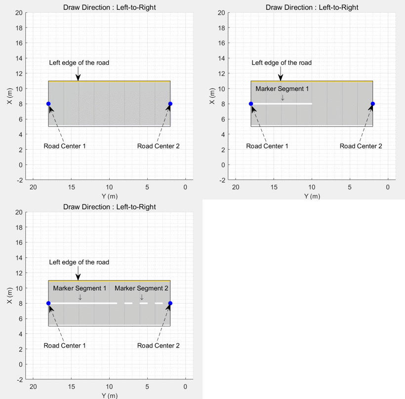
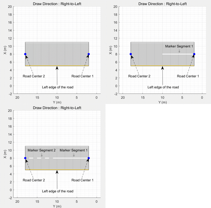
| Lane Markings > Specify multiple marker types along a lane | Select this parameter to define composite lane markings. A composite lane marking comprises multiple marker types along a lane. The portion of the lane marking that contains each marker type is referred as a marker segment. For more information on composite lane markings, see Composite Lane Marking. | ||||||||||||
| Lane Markings > Number of Marker Segments | Number of marker segments in a composite lane marking, specified as an integer greater than or equal to 2. A composite lane marking must have at least two marker segments. The app supports a maximum of 10 marker segments for every 1 meter of road length. For example, when you specify composite lane marking for a 10-meter road segment, the number of marker segments must be less than or equal to 100. Default:
Dependencies To enable this parameter, select the Specify multiple marker types along a lane parameter. | ||||||||||||
| Lane Markings > Segment Range | Normalized range for each marker segment in a composite lane marking, specified as a row vector of values in the range [0, 1]. The length of the vector must be equal to the Number of Marker Segments parameter value. Default: Dependencies To enable this parameter, select the Specify multiple marker types along a lane parameter. | ||||||||||||
| Lane Markings > Marker Segment | Marker segments, specified as a list of marker types in the selected lane marking. To modify one or more marker segment parameters that include marking type, color, and strength, select the desired marker segment from the drop-down list. Dependencies To enable this parameter, select the Specify multiple marker types along a lane parameter. | ||||||||||||
| Lane Markings > Type | Type of lane marking, specified as one of these values:
By default, for a one-way road, the leftmost lane marking is a solid yellow line, the rightmost lane marking is a solid white line, and the markings for the inner lanes are dashed white lines. For two-way roads, the default outermost lane markings are both solid white lines and the dividing lane marking is two solid yellow lines. If you enable the Specify multiple marker types along a lane parameter, then this value is applied to the selected marker segment in a composite lane marking. | ||||||||||||
| Lane Markings > Color | Color of lane marking, specified as an RGB triplet, hexadecimal color code, color name, or short color name. For a lane marker specifying a double line, the same color is used for both lines. You can also specify some common colors as an RGB triplet, hexadecimal color code, color name, or short color name. For more information, see Color Specifications for Lanes and Markings. If you enable the Specify multiple marker types along a lane parameter, then this value is applied to the selected marker segment in a composite lane marking. | ||||||||||||
| Lane Markings > Strength | Saturation strength of lane marking color, specified as a decimal scalar in the range [0, 1].
For a lane marker specifying a double line, the same strength is used for both lines. Default:
If you enable the Specify multiple marker types along a lane parameter, then this value is applied to the selected marker segment in a composite lane marking. | ||||||||||||
| Lane Markings > Width (m) | Width of lane marking, in meters, specified as a positive decimal scalar. The width of the lane marking must be less than the width of its enclosing lane. The enclosing lane is the lane directly to the left of the lane marking. For a lane marker specifying a double line, the same width is used for both lines. Default:
If you enable the Specify multiple marker types along a lane parameter, then this value is applied to the selected marker segment in a composite lane marking. | ||||||||||||
| Lane Markings > Length (m) | Length of dashes in dashed lane markings, in meters, specified as a decimal scalar in the range (0, 50]. For a lane marker specifying a double line, the same length is used for both lines. Default:
If you enable the Specify multiple marker types along a lane parameter, then this value is applied to the selected marker segment in a composite lane marking. | ||||||||||||
| Lane Markings > Space (m) | Length of spaces between dashes in dashed lane markings, in meters, specified as a decimal scalar in the range (0, 150]. For a lane marker specifying a double line, the same space is used for both lines. Default:
If you enable the Specify multiple marker types along a lane parameter, then this value is applied to the selected marker segment in a composite lane marking. |
To enable the Segment Taper parameters,
specify a Number of Road Segments parameter
value greater than 1, and specify a distinct
value for either the Number of Lanes or
Lane Width (m) parameter of at least
one road segment. Then, select a taper from the drop-down list
to specify taper parameters.
A road with N road segments has (N – 1) segment tapers. The Lth taper, where L < N, is part of the Lth road segment.
| Parameter | Description |
|---|---|
| Shape | Taper shape of the road segment,
specified as either Default:
|
| Length (m) | Taper length of the road segment, specified as a positive scalar. Units are in meters. The default taper length is
the smaller of The
specified taper length must be less than the
length of the corresponding road segment.
Otherwise, the app resets it to a value that is
Dependencies To
enable this parameter, set the
Shape parameter to
|
| Position | Edge of the road segment from which to add or drop lanes, specified as one of these values:
You can specify the value of this parameter for connecting two one-way road segments. When connecting two-way road segments to each other, or one-way road segments to two-way road segments, the app determines the value of this parameter based on the specified Number of Lanes parameter. To add or drop lanes from both edges of a one-way road segment, the number of lanes in the one-way road segments must differ by an even number. Default:
Dependencies To enable this parameter, specify different integer scalars for the Number of Lanes parameters of different road segments. |
Use these parameters to specify the orientation of the road.
| Parameter | Description |
|---|---|
| Bank Angle (deg) | Side-to-side incline of the road, in degrees, specified as one of these values:
When you add an actor to a road, you do not have to change the actor position to match the bank angles specified by this parameter. The actor automatically follows the bank angles of the road. Default:
|
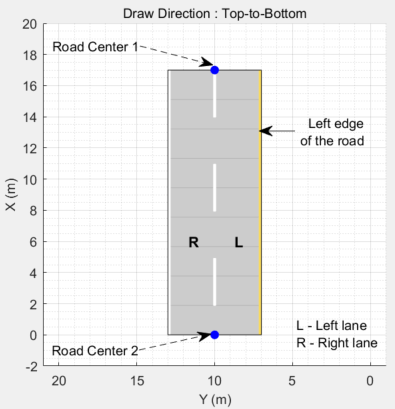
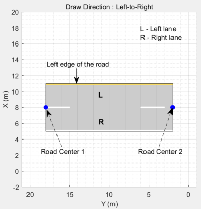
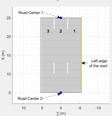
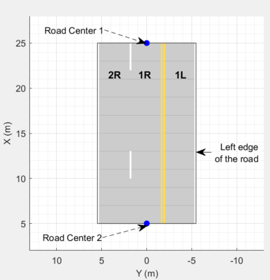
Each row of the Road Centers table contains the x-, y-, and z-positions, as well as the heading angle, of a road center within the selected road. All roads must have at least two unique road center positions. When you update a cell within the table, the Scenario Canvas updates to reflect the new road center position. The orientation of the road depends on the values of the road centers and the heading angles. The road centers specify the direction in which the road renders in the Scenario Canvas. For more information, see Draw Direction of Road and Numbering of Lanes.
| Parameter | Description |
|---|---|
| x (m) | x-axis position of the road center, in meters, specified as a decimal scalar. |
| y (m) | y-axis position of the road center, in meters, specified as a decimal scalar. |
| z (m) | z-axis position of the road center, in meters, specified as a decimal scalar.
Default:
|
| heading (°) | Heading angle of the road about its x-axis at the road center, in degrees, specified as a decimal scalar. When you specify a heading angle, it acts as a constraint on that road center point and the app automatically determines the other heading angles. Specifying heading angles enables finer control over the shape and orientation of the road in the Scenario Canvas. For more information, see Heading Angle. When you export the driving scenario to a MATLAB function and run that function, MATLAB wraps the heading angles of the road in the output scenario, to the range [–180, 180]. |
Each row of the Road Group Centers table
contains the x-, y-, and
z-positions of a center within the
selected intersection of an imported road network. These center
location parameters are read-only parameters since intersections
cannot be created interactively. Use the roadGroup function to add an intersection to the
scenario programmatically.
| Parameter | Description |
|---|---|
| x (m) | x-axis position of the intersection center, in meters, specified as a decimal scalar. |
| y (m) | y-axis position of the intersection center, in meters, specified as a decimal scalar. |
| z (m) | z-axis position of the road center, in meters, specified as a decimal scalar.
Dependencies To enable this parameter, select the intersection from the Scenario Canvas. The app enables this parameter for these cases only:
|
To enable the Actors parameters, add at least one actor to the scenario. Then, select an actor from either the Scenario Canvas or from the list on the Actors tab. The parameter values in the Actors tab are based on the actor you select. If you select multiple actors, then many of these parameters are disabled.
| Parameter | Description | ||||||||||||||
|---|---|---|---|---|---|---|---|---|---|---|---|---|---|---|---|
| Color | To change the color of an actor, next to the actor selection list, click the color patch for that actor.
Then, use the color picker to select
one of the standard colors commonly used in MATLAB graphics. Alternatively, select a custom
color from the Custom Colors tab
by first clicking By default, the app sets each newly
created actor to a new color. This color order is based
on the default color order of To set a single default color for all newly created actors of a specific class, on the app toolstrip, select Add Actor > Edit Actor Classes. Then, select Set Default Color and click the corresponding color patch to set the color. To select a default color for a class, the Scenario Canvas must contain no actors of that class. Color changes made in the app are carried forward into Bird's-Eye Scope visualizations. | ||||||||||||||
| Set as Ego Vehicle | Set the selected actor as the ego vehicle in the scenario. When you add sensors to your scenario, the app adds them to the ego vehicle. In addition, the Ego-Centric View and Bird's-Eye Plot windows display simulations from the perspective of the ego vehicle. Only actors who have vehicle
classes, such as For more details on actor classes, see the Class parameter description. | ||||||||||||||
| Name | Name of actor. | ||||||||||||||
| Class | Class of actor, specified as the list of classes to which you can change the selected actor. You
can change the class of vehicle actors only to other
vehicle classes. The default vehicle classes are
The list of vehicle and nonvehicle classes appear in the app toolstrip, in the Add Actor > Vehicles and Add Actor > Other or Add Actor > Barriers sections, respectively. Actors created in the app have default sets of dimensions, radar cross-section patterns, and other properties based on their Class ID value. The table shows the default Class ID values and actor classes.
To modify actor classes or create new actor classes, on the app toolstrip, select Add Actor > Edit Actor Classes or Add Actor > New Actor Class, respectively. | ||||||||||||||
| 3D Display Type | Display type of actor as it appears in the 3D display window, specified as the list of display types to which you can change the selected actor. To display the scenario in the 3D display window during simulation, on the app toolstrip, click 3D Display > View Simulation in 3D Display. The app renders this display by using the Unreal Engine® from Epic Games®. For any actor, the available 3D Display Type options depend on the actor class specified in the Class parameter.
If you change the dimensions of an
actor using the Actor Properties
parameters, the app applies these changes in the
Scenario Canvas display but not
in the 3D display. This case does not apply to actors
whose 3D Display Type is set to
In the 3D display, actors of all other display types have predefined dimensions. To use the same dimensions in both displays, you can apply the predefined 3D display dimensions to the actors in the Scenario Canvas display. On the app toolstrip, under 3D Display, select Use 3D Simulation Actor Dimensions. |
Use these parameters to specify properties such as the position and orientation of an actor.
| Parameter | Description |
|---|---|
| Length (m) | Length of actor, in meters, specified as a decimal scalar in the range (0, 60]. For vehicles, the length must be greater than (Front Overhang + Rear Overhang). |
| Width (m) | Width of actor, in meters, specified as a decimal scalar in the range (0, 20]. |
| Height (m) | Height of actor, in meters, specified as a decimal scalar in the range (0, 20]. |
| Front Overhang | Distance between the front axle and front bumper, in meters, specified as a decimal scalar. The front overhang must be less than (Length (m) – Rear Overhang). This parameter applies to vehicles only. Default:
|
| Rear Overhang | Distance between the rear axle and rear bumper, in meters, specified as a decimal scalar. The rear overhang must be less than (Length (m) – Front Overhang). This parameter applies to vehicles only. Default:
|
| Roll (°) | Orientation angle of the actor about its x-axis, in degrees, specified as a decimal scalar. Roll (°) is clockwise-positive when looking in the forward direction of the x-axis, which points forward from the actor. When you export the MATLAB function of the driving scenario and run that function, the roll angles of actors in the output scenario are wrapped to the range [–180, 180]. Default:
|
| Pitch (°) | Orientation angle of the actor about its y-axis, in degrees, specified as a decimal scalar. Pitch (°) is clockwise-positive when looking in the forward direction of the y-axis, which points to the left of the actor. When you export the MATLAB function of the driving scenario and run that function, the pitch angles of actors in the output scenario are wrapped to the range [–180, 180]. Default:
|
| Yaw (°) | Orientation angle of the actor about its z-axis, in degrees, specified as a decimal scalar. Yaw (°) is clockwise-positive when looking in the forward direction of the z-axis, which points up from the ground. However, the Scenario Canvas has a bird's-eye-view perspective that looks in the reverse direction of the z-axis. Therefore, when viewing actors on this canvas, Yaw (°) is counterclockwise-positive. When you export the MATLAB function of the driving scenario and run that function, the yaw angles of actors in the output scenario are wrapped to the range [–180, 180]. Default:
|
Use these parameters to manually specify the radar cross-section (RCS) of an actor. Alternatively, to import an RCS from a file or from the MATLAB workspace, expand this parameter section and click Import.
| Parameter | Description |
|---|---|
| Azimuth Angles (deg) | Horizontal reflection pattern of actor, in degrees, specified as a vector of monotonically increasing decimal values in the range [–180, 180]. Default: |
| Elevation Angles (deg) | Vertical reflection pattern of actor, in degrees, specified as a vector of monotonically increasing decimal values in the range [–90, 90]. Default: |
| Pattern (dBsm) | RCS pattern, in decibels per square meter, specified as a Q-by-P table of decimal values. RCS is a function of the azimuth and elevation angles, where:
|
Use the Waypoints, Speeds, Wait Times, and
Yaw table to manually set or modify the
positions, speeds, wait times, and yaw orientation angles of
actors at their specified waypoints. When specifying
trajectories, to switch between adding forward and reverse
motion waypoints, use the add forward and reverse motion
waypoint buttons ![]() .
.
| Parameter | Description |
|---|---|
| Constant Speed (m/s) | Default speed of actors as you add waypoints, specified as a positive decimal scalar in meters per second. If you set specific speed values in the v (m/s) column of the Waypoints, Speeds, Wait Times, and Yaw table, then the app clears the Constant Speed (m/s) value. If you then specify a new Constant Speed (m/s) value, then the app sets all waypoints to the new constant speed value. The default speed of an actor varies by actor class. For example, cars and trucks have a default constant speed of 30 meters per second, whereas pedestrians have a default constant speed of 1.5 meters per second. |
| Waypoints, Speeds, Wait Times, and Yaw | Actor waypoints, specified as a table. Each row corresponds to a waypoint and contains the position, speed, and orientation of the actor at that waypoint. The table has these columns:
|
| Use smooth, jerk-limited trajectory | Select this parameter to specify a smooth trajectory for the actor. Smooth trajectories have no discontinuities in acceleration and are required for INS sensor simulation. If you mount an INS sensor to the ego vehicle, then the app updates the ego vehicle to use a smooth trajectory. If the app is unable to generate a smooth trajectory, try making these adjustments:
The app computes
smooth trajectories by using the Default:
|
| Jerk (m/s3) | Maximum longitudinal jerk of the actor, in meters per second cubed, specified as a real-valued scalar greater than or equal to 0.1. |
Actor Spawn and Despawn During Simulation
| Parameter | Description |
|---|---|
| Actor spawn and despawn | Select this parameter to spawn or despawn an actor in the driving scenario, while the simulation is running. To enable this parameter, you must first select an actor in the scenario by clicking on the actor. Specify values for the Entry Time (s) and Exit Time (s) parameters to make the actor enter (spawn) and exit (despawn) the scenario, respectively. Default:
|
| Entry Time (s) | Entry time at which an actor spawns into the scenario during simulation, specified as one of these values:
The default value for entry
time is |
| Exit Time (s) | Exit time at which an actor despawns from the scenario during simulation, specified as one of these values:
The default value for exit
time is |
To get expected spawning and despawning behavior, the Entry Time (s) and Exit Time (s) parameters must satisfy these conditions:
Each value for the Entry Time (s) parameter must be less than the corresponding value for the Exit Time (s) parameter.
Each value for the Entry Time (s) and the Exit Time (s) parameters must be less than the entire simulation time that is set by either the stop condition or the stop time.
When the Entry Time (s) and Exit Time (s) parameters are specified as vectors:
The elements of each vector must be in ascending order.
The lengths of both the vectors must be the same.
To enable the Barriers parameters, add at least one barrier to the scenario. Then, select a barrier from either the Scenario Canvas or from the Barriers tab. The parameter values in the Barriers tab are based on the barrier you select.
| Parameter | Description |
|---|---|
| Color | To change the color of a barrier, next to the actor selection list, click the color patch for that barrier. Then, use the color picker to
select one of the standard colors commonly used in
MATLAB graphics. Alternatively, select a custom
color from the Custom Colors tab
by first clicking Color changes made in the app are carried forward into Bird's-Eye Scope visualizations. |
| Name | Name of barrier |
| Bank Angle (°) | Side-to-side incline of the barrier, in degrees, specified as one of these values:
This property is valid only when you add a barrier using barrier centers. When you add a barrier to a road, the barrier automatically takes the bank angles of the road. Default:
|
| Barrier Type | Barrier type, specified as one of the following options:
|
Use these parameters to specify physical properties of the barrier.
| Parameter | Description |
|---|---|
| Width (m) | Width of the barrier, in meters, specified as a decimal scalar in the range (0,20]. Default:
|
| Height (m) | Height of the barrier, in meters, specified as a decimal scalar in the range (0,20]. Default:
|
| Segment Length (m) | Length of each barrier segment, in meters, specified as a decimal scalar in the range (0,100]. Default:
|
| Segment Gap (m) | Gap between consecutive barrier
segments, in meters, specified as a decimal scalar
in the range [0, Default:
|
Use these parameters to manually specify the radar cross-section (RCS) of a barrier. Alternatively, to import an RCS from a file or from the MATLAB workspace, expand this parameter section and click Import.
| Parameter | Description |
|---|---|
| Azimuth Angles (deg) | Horizontal reflection pattern of barrier, in degrees, specified as a vector of monotonically increasing decimal values in the range [–180, 180]. Default: |
| Elevation Angles (deg) | Vertical reflection pattern of barrier, in degrees, specified as a vector of monotonically increasing decimal values in the range [–90, 90]. Default: |
| Pattern (dBsm) | RCS pattern, in decibels per square meter, specified as a Q-by-P table of decimal values. RCS is a function of the azimuth and elevation angles, where:
|
Each row of the Barrier Centers table contains the x-, y-, and z-positions of a barrier center within the selected barrier. All barriers must have at least two unique barrier center positions. When you update a cell within the table, the Scenario Canvas updates to reflect the new barrier center position. The orientation of the barrier depends on the values of the barrier centers. The barrier centers specifies the direction in which the barrier renders in the Scenario Canvas.
| Parameter | Description |
|---|---|
| Road Edge Offset (m) | Distance by which the barrier is offset from the road edge in the lateral direction, in meters, specified as a decimal scalar. |
| x (m) | x-axis position of the barrier center, in meters, specified as a decimal scalar. |
| y (m) | y-axis position of the barrier center, in meters, specified as a decimal scalar. |
| z (m) | z-axis position of the barrier center, in meters, specified as a decimal scalar. Default:
|
To access these parameters, add at least one camera sensor to the scenario by following these steps:
On the app toolstrip, click Add Camera.
From the Sensors tab, select the sensor from the list. The parameter values in this tab are based on the sensor you select.
| Parameter | Description |
|---|---|
| Enabled | Enable or disable the selected sensor. Select this parameter to capture sensor data during simulation and visualize that data in the Bird's-Eye Plot pane. |
| Name | Name of sensor. |
| Update Interval (ms) | Frequency at which the sensor updates, in milliseconds, specified as an integer multiple of the app sample time defined under Settings, in the Sample Time (ms) parameter. The
default Update Interval (ms) value of
If you update the app sample time such that a sensor is no longer a multiple of the app sample time, the app prompts you with the option to automatically update the Update Interval (ms) parameter to the closest integer multiple. Default:
|
| Type | Type of sensor, specified as Radar, Vision, Lidar, INS, or Ultrasonic. |
Use these parameters to set the position and orientation of the selected camera sensor.
| Parameter | Description |
|---|---|
| X (m) | X-axis position of the sensor in the vehicle coordinate system, in meters, specified as a decimal scalar. The X-axis points forward from the vehicle. The origin is located at the center of the vehicle's rear axle. |
| Y (m) | Y-axis position of the sensor in the vehicle coordinate system, in meters, specified as a decimal scalar. The Y-axis points to the left of the vehicle. The origin is located at the center of the vehicle's rear axle. |
| Height (m) | Height of the sensor above the ground, in meters, specified as a positive decimal scalar. |
| Roll (°) | Orientation angle of the sensor about its X-axis, in degrees, specified as a decimal scalar. Roll (°) is clockwise-positive when looking in the forward direction of the X-axis, which points forward from the sensor. |
| Pitch (°) | Orientation angle of the sensor about its Y-axis, in degrees, specified as a decimal scalar. Pitch (°) is clockwise-positive when looking in the forward direction of the Y-axis, which points to the left of the sensor. |
| Yaw (°) | Orientation angle of the sensor about its Z-axis, in degrees, specified as a decimal scalar. Yaw (°) is clockwise-positive when looking in the forward direction of the Z-axis, which points up from the ground. The Sensor Canvas has a bird's-eye-view perspective that looks in the reverse direction of the Z-axis. Therefore, when viewing sensor coverage areas on this canvas, Yaw (°) is counterclockwise-positive. |
Use these parameters to set the intrinsic parameters of the camera sensor.
| Parameter | Description |
|---|---|
| Focal Length X | Horizontal point at which the camera is in focus, in pixels, specified as a positive decimal scalar. The default focal length changes depending on where you place the sensor on the ego vehicle. |
| Focal Length Y | Vertical point at which the camera is in focus, in pixels, specified as a positive decimal scalar. The default focal length changes depending on where you place the sensor on the ego vehicle. |
| Image Width | Horizontal camera resolution, in pixels, specified as a positive integer. Default:
|
| Image Height | Vertical camera resolution, in pixels, specified as a positive integer. Default:
|
| Principal Point X | Horizontal image center, in pixels, specified as a positive decimal scalar. Default:
|
| Principal Point Y | Vertical image center, in pixels, specified as a positive decimal scalar. Default:
|
To view all camera detection parameters in the app, expand the Sensor Limits, Lane Settings, and Accuracy & Noise Settings sections.
| Parameter | Description |
|---|---|
| Detection Type | Type of detections reported by camera, specified as one of these values:
Default:
|
| Detection Probability | Probability that the camera detects an object, specified as a decimal scalar in the range (0, 1]. Default:
|
| False Positives Per Image | Number of false positives reported per update interval, specified as a nonnegative decimal scalar. This value must be less than or equal to the maximum number of detections specified in the Limit # of Detections parameter. Default:
|
| Limit # of Detections | Select this parameter to limit the number of simultaneous object detections that the sensor reports. Specify Limit # of Detections as a positive integer less than 263. To
enable this parameter, set the Detection
Type parameter to
Default:
|
| Detection Coordinates | Coordinate system of output detection locations, specified as one of these values:
Default: |
Sensor Limits
| Parameter | Description |
|---|---|
| Max Speed (m/s) | Fastest relative speed at which the camera can detect objects, in meters per second, specified as a nonnegative decimal scalar. Default:
|
| Max Range (m) | Farthest distance at which the camera can detect objects, in meters, specified as a positive decimal scalar. Default:
|
| Max Allowed Occlusion | Maximum percentage of object that can be blocked while still being detected, specified as a decimal scalar in the range [0, 1). Default:
|
| Min Object Image Width | Minimum horizontal size of objects that the camera can detect, in pixels, specified as positive decimal scalar. Default:
|
| Min Object Image Height | Minimum vertical size of objects that the camera can detect, in pixels, specified as positive decimal scalar. Default:
|
Lane Settings
| Parameter | Description |
|---|---|
| Lane Update Interval (ms) | Frequency at which the sensor updates lane detections, in milliseconds, specified as a decimal scalar. Default:
|
| Min Lane Image Width | Minimum horizontal size of objects that the sensor can detect, in pixels, specified as a decimal scalar. To enable this
parameter, set the Detection
Type parameter to
Default:
|
| Min Lane Image Height | Minimum vertical size of objects that the sensor can detect, in pixels, specified as a decimal scalar. To enable this
parameter, set the Detection
Type parameter to
Default:
|
| Boundary Accuracy | Accuracy with which the sensor places a lane boundary, in pixels, specified as a decimal scalar. To enable this parameter, set
the Detection Type parameter
to Default:
|
| Limit # of Lanes | Select this parameter to limit the number of lane detections that the sensor reports. Specify Limit # of Lanes as a positive integer. To enable this
parameter, set the Detection
Type parameter to
Default:
|
Accuracy & Noise Settings
| Parameter | Description |
|---|---|
| Bounding Box Accuracy | Positional noise used for fitting bounding boxes to targets, in pixels, specified as a positive decimal scalar. Default:
|
| Process Noise Intensity (m/s^2) | Noise intensity used for smoothing position and velocity measurements, in meters per second squared, specified as a positive decimal scalar. Default:
|
| Has Noise | Select this parameter to enable adding noise to sensor measurements. Default:
|
To access these parameters, add at least one radar sensor to the scenario.
On the app toolstrip, click Add Radar.
On the Sensors tab, select the sensor from the list. The parameter values change based on the sensor you select.
| Parameter | Description |
|---|---|
| Enabled | Enable or disable the selected sensor. Select this parameter to capture sensor data during simulation and visualize that data in the Bird's-Eye Plot pane. |
| Name | Name of sensor. |
| Update Interval (ms) | Frequency at which the sensor updates, in milliseconds, specified as an integer multiple of the app sample time defined under Settings, in the Sample Time (ms) parameter. The
default Update Interval (ms) value of
If you update the app sample time such that a sensor is no longer a multiple of the app sample time, the app prompts you with the option to automatically update the Update Interval (ms) parameter to the closest integer multiple. Default:
|
| Type | Type of sensor, specified as Radar, Vision, Lidar, INS, or Ultrasonic. |
Use these parameters to set the position and orientation of the selected radar sensor.
| Parameter | Description |
|---|---|
| X (m) | X-axis position of the sensor in the vehicle coordinate system, in meters, specified as a decimal scalar. The X-axis points forward from the vehicle. The origin is located at the center of the vehicle's rear axle. |
| Y (m) | Y-axis position of the sensor in the vehicle coordinate system, in meters, specified as a decimal scalar. The Y-axis points to the left of the vehicle. The origin is located at the center of the vehicle's rear axle. |
| Height (m) | Height of the sensor above the ground, in meters, specified as a positive decimal scalar. |
| Roll (°) | Orientation angle of the sensor about its X-axis, in degrees, specified as a decimal scalar. Roll (°) is clockwise-positive when looking in the forward direction of the X-axis, which points forward from the sensor. |
| Pitch (°) | Orientation angle of the sensor about its Y-axis, in degrees, specified as a decimal scalar. Pitch (°) is clockwise-positive when looking in the forward direction of the Y-axis, which points to the left of the sensor. |
| Yaw (°) | Orientation angle of the sensor about its Z-axis, in degrees, specified as a decimal scalar. Yaw (°) is clockwise-positive when looking in the forward direction of the Z-axis, which points up from the ground. The Sensor Canvas has a bird's-eye-view perspective that looks in the reverse direction of the Z-axis. Therefore, when viewing sensor coverage areas on this canvas, Yaw (°) is counterclockwise-positive. |
To view all radar detection parameters in the app, expand the Advanced Parameters and Accuracy & Noise Settings sections.
| Parameter | Description |
|---|---|
| Detection Probability | Probability that the radar detects an object, specified as a decimal scalar in the range (0, 1]. Default:
|
| False Alarm Rate | Probability of a false detection per resolution rate, specified as a decimal scalar in the range [1e-07, 1e-03]. Default:
|
| Field of View Azimuth | Horizontal field of view of radar, in degrees, specified as a positive decimal scalar. Default:
|
| Field of View Elevation | Vertical field of view of radar, in degrees, specified as a positive decimal scalar. Default:
|
| Max Range (m) | Farthest distance at which the radar can detect objects, in meters, specified as a positive decimal scalar. Default:
|
| Range Rate Min, Range Rate Max | Select this parameter to set minimum and maximum range rate limits for the radar. Specify Range Rate Min and Range Rate Max as decimal scalars, in meters per second, where Range Rate Min is less than Range Rate Max. Default (Min):
Default (Max):
|
| Has Elevation | Select this parameter to enable the radar to measure the elevation of objects. This parameter enables the elevation parameters in the Accuracy & Noise Settings section. Default:
|
| Has Occlusion | Select this parameter to enable the radar to model occlusion. Default:
|
Advanced Parameters
| Parameter | Description |
|---|---|
| Reference Range | Reference range for a given probability of detection, in meters, specified as a positive decimal scalar. The reference range is the range at which the radar detects a target of the size specified by Reference RCS, given the probability of detection specified by Detection Probability. Default:
|
| Reference RCS | Reference RCS for a given probability of detection, in decibels per square meter, specified as a nonnegative decimal scalar. The reference RCS is the target size at which the radar detects a target, given the reference range specified by Reference Range and the probability of detection specified by Detection Probability. Default:
|
| Limit # of Detections | Select this parameter to limit the number of simultaneous detections that the sensor reports. Specify Limit # of Detections as a positive integer less than 263. Default:
|
| Detection Coordinates | Coordinate system of output detection locations, specified as one of these values:
Default: |
Accuracy & Noise Settings
| Parameter | Description |
|---|---|
| Azimuth Resolution | Minimum separation in azimuth angle at which the radar can distinguish between two targets, in degrees, specified as a positive decimal scalar. The azimuth resolution is typically the 3 dB downpoint in the azimuth angle beamwidth of the radar. Default:
|
| Azimuth Bias Fraction | Maximum azimuth accuracy of the radar, specified as a nonnegative decimal scalar. The azimuth bias is expressed as a fraction of the azimuth resolution specified by the Azimuth Resolution parameter. Units are dimensionless. Default:
|
| Elevation Resolution | Minimum separation in elevation angle at which the radar can distinguish between two targets, in degrees, specified as a positive decimal scalar. The elevation resolution is typically the 3 dB downpoint in the elevation angle beamwidth of the radar. To enable this parameter, in the Sensor Parameters section, select the Has Elevation parameter. Default:
|
| Elevation Bias Fraction | Maximum elevation accuracy of the radar, specified as a nonnegative decimal scalar. The elevation bias is expressed as a fraction of the elevation resolution specified by the Elevation Resolution parameter. Units are dimensionless. To enable this parameter, under Sensor Parameters, select the Has Elevation parameter. Default:
|
| Range Resolution | Minimum range separation at which the radar can distinguish between two targets, in meters, specified as a positive decimal scalar. Default:
|
| Range Bias Fraction | Maximum range accuracy of the radar, specified as a nonnegative decimal scalar. The range bias is expressed as a fraction of the range resolution specified in the Range Resolution parameter. Units are dimensionless. Default:
|
| Range Rate Resolution | Minimum range rate separation at which the radar can distinguish between two targets, in meters per second, specified as a positive decimal scalar. To enable this parameter, in the Sensor Parameters section, select the Range Rate Min, Range Rate Max parameter and set the range rate values. Default:
|
| Range Rate Bias Fraction | Maximum range rate accuracy of the radar, specified as a nonnegative decimal scalar. The range rate bias is expressed as a fraction of the range rate resolution specified in the Range Rate Resolution parameter. Units are dimensionless. To enable this parameter, in the Sensor Parameters section, select the Range Rate Min, Range Rate Max parameter and set the range rate values. Default:
|
| Has Noise | Select this parameter to enable adding noise to sensor measurements. Default:
|
| Has False Alarms | Select this parameter to enable false alarms in sensor detections. Default:
|
To access these parameters, add at least one lidar sensor to the scenario.
On the app toolstrip, click Add Lidar.
On the Sensors tab, select the sensor from the list. The parameter values change based on the sensor you select.
When you add a lidar sensor to a scenario, the Bird's-Eye Plot and Ego-Centric View display the mesh representations of actors. For example, here is a sample view of actor meshes on the Ego-Centric View.
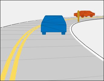
The lidar sensors use these more detailed representations of actors to generate point cloud data. The Scenario Canvas still displays only the cuboid representations. The other sensors still base their detections on the cuboid representations.
To turn off actor meshes, use the properties under Display on the app toolstrip. To modify the mesh display types of actors, select Add Actor > Edit Actor Classes. In the Class Editor, modify the Mesh Display Type parameter of that actor class.
| Parameter | Description |
|---|---|
| Enabled | Enable or disable the selected sensor. Select this parameter to capture sensor data during simulation and visualize that data in the Bird's-Eye Plot pane. |
| Name | Name of sensor. |
| Update Interval (ms) | Frequency at which the sensor updates, in milliseconds, specified as an integer multiple of the app sample time defined under Settings, in the Sample Time (ms) parameter. The
default Update Interval (ms) value of
If you update the app sample time such that a sensor is no longer a multiple of the app sample time, the app prompts you with the option to automatically update the Update Interval (ms) parameter to the closest integer multiple. Default:
|
| Type | Type of sensor, specified as Radar, Vision, Lidar, INS, or Ultrasonic. |
Use these parameters to set the position and orientation of the selected lidar sensor.
| Parameter | Description |
|---|---|
| X (m) | X-axis position of the sensor in the vehicle coordinate system, in meters, specified as a decimal scalar. The X-axis points forward from the vehicle. The origin is located at the center of the vehicle's rear axle. |
| Y (m) | Y-axis position of the sensor in the vehicle coordinate system, in meters, specified as a decimal scalar. The Y-axis points to the left of the vehicle. The origin is located at the center of the vehicle's rear axle. |
| Height (m) | Height of the sensor above the ground, in meters, specified as a positive decimal scalar. |
| Roll (°) | Orientation angle of the sensor about its X-axis, in degrees, specified as a decimal scalar. Roll (°) is clockwise-positive when looking in the forward direction of the X-axis, which points forward from the sensor. |
| Pitch (°) | Orientation angle of the sensor about its Y-axis, in degrees, specified as a decimal scalar. Pitch (°) is clockwise-positive when looking in the forward direction of the Y-axis, which points to the left of the sensor. |
| Yaw (°) | Orientation angle of the sensor about its Z-axis, in degrees, specified as a decimal scalar. Yaw (°) is clockwise-positive when looking in the forward direction of the Z-axis, which points up from the ground. The Sensor Canvas has a bird's-eye-view perspective that looks in the reverse direction of the Z-axis. Therefore, when viewing sensor coverage areas on this canvas, Yaw (°) is counterclockwise-positive. |
| Parameter | Description |
|---|---|
| Detection Coordinates | Coordinate system of output detection locations, specified as one of these values:
Default: |
| Output organized point cloud locations | Select this parameter to output the generated sensor data as an organized point cloud. If you clear this parameter, the output is unorganized. Default:
|
| Include ego vehicle in generated point cloud | Select this parameter to include the ego vehicle in the generated point cloud. Default:
|
| Include roads in generated point cloud | Select this parameter to include roads in the generated point cloud. Default:
|
Sensor Limits
| Parameter | Description |
|---|---|
| Max Range (m) | Farthest distance at which the lidar can detect objects, in meters, specified as a positive decimal scalar. Default:
|
| Range Accuracy (m) | Accuracy of range measurements, in meters, specified as a positive decimal scalar. Default:
|
| Azimuth | Azimuthal resolution of the lidar sensor, in degrees, specified as a positive decimal scalar. The azimuthal resolution defines the minimum separation in azimuth angle at which the lidar can distinguish two targets. Default:
|
| Elevation | Elevation resolution of the lidar sensor, in degrees, specified as a positive decimal scalar. The elevation resolution defines the minimum separation in elevation angle at which the lidar can distinguish two targets. Default:
|
| Azimuthal Limits (deg) | Azimuthal limits of the lidar sensor,
in degrees, specified as a two-element vector of
decimal scalars of the form Default: |
| Elevation Limits (deg) | Elevation limits of the lidar sensor,
in degrees, specified as a two-element vector of
decimal scalars of the form Default: |
| Has Noise | Select this parameter to enable adding noise to sensor measurements. Default:
|
To access these parameters, add at least one INS sensor to the scenario by following these steps:
On the app toolstrip, click Add INS.
From the Sensors tab, select the sensor from the list. The parameter values in this tab are based on the sensor you select.
| Parameter | Description |
|---|---|
| Enabled | Enable or disable the selected sensor. Select this parameter to capture sensor data during simulation and visualize that data in the Bird's-Eye Plot pane. |
| Name | Name of sensor. |
| Update Interval (ms) | Frequency at which the sensor updates, in milliseconds, specified as an integer multiple of the app sample time defined under Settings, in the Sample Time (ms) parameter. The
default Update Interval (ms) value of
If you update the app sample time such that a sensor is no longer a multiple of the app sample time, the app prompts you with the option to automatically update the Update Interval (ms) parameter to the closest integer multiple. Default:
|
| Type | Type of sensor, specified as Radar, Vision, Lidar, INS, or Ultrasonic. |
Use these parameters to set the position of the selected INS sensor. The orientation of the sensor is assumed to be aligned with the ego vehicle origin, so the Roll (°), Pitch (°), and Yaw (°) properties are disabled for this sensor.
| Parameter | Description |
|---|---|
| X (m) | X-axis position of the sensor in the vehicle coordinate system, in meters, specified as a decimal scalar. The X-axis points forward from the vehicle. The origin is located at the center of the vehicle's rear axle. |
| Y (m) | Y-axis position of the sensor in the vehicle coordinate system, in meters, specified as a decimal scalar. The Y-axis points to the left of the vehicle. The origin is located at the center of the vehicle's rear axle. |
| Height (m) | Height of the sensor above the ground, in meters, specified as a positive decimal scalar. |
| Roll (°) | Orientation angle of the sensor about its X-axis, in degrees, specified as a decimal scalar. Roll (°) is clockwise-positive when looking in the forward direction of the X-axis, which points forward from the sensor. |
| Pitch (°) | Orientation angle of the sensor about its Y-axis, in degrees, specified as a decimal scalar. Pitch (°) is clockwise-positive when looking in the forward direction of the Y-axis, which points to the left of the sensor. |
| Yaw (°) | Orientation angle of the sensor about its Z-axis, in degrees, specified as a decimal scalar. Yaw (°) is clockwise-positive when looking in the forward direction of the Z-axis, which points up from the ground. The Sensor Canvas has a bird's-eye-view perspective that looks in the reverse direction of the Z-axis. Therefore, when viewing sensor coverage areas on this canvas, Yaw (°) is counterclockwise-positive. |
For additional details about these parameters, see the insSensor object reference page.
| Parameter | Description |
|---|---|
| Roll Accuracy (°) | Roll accuracy, in degrees, specified as a nonnegative decimal scalar. This value sets the standard deviation of the roll measurement noise. Default:
|
| Pitch Accuracy (°) | Pitch accuracy, in degrees, specified as a nonnegative decimal scalar. This value sets the standard deviation of the pitch measurement noise. Default:
|
| Yaw Accuracy (°) | Yaw accuracy, in degrees, specified as a nonnegative decimal scalar. This value sets the standard deviation of the yaw measurement noise. Default:
|
| Position Accuracy (m) | Accuracy of x-, y-, and z-position measurements, in meters, specified as a decimal scalar or three-element decimal scalar. This value sets the standard deviation of the position measurement noise. Specify a scalar to set the accuracy of all three positions to this value. Default: |
| Velocity Accuracy (m/s) | Accuracy of velocity measurements, in meters per second, specified as a decimal scalar. This value sets the standard deviation of the velocity measurement noise. Default:
|
| Acceleration Accuracy | Accuracy of acceleration measurements, in meters per second squared, specified as a decimal scalar. This value sets the standard deviation of the acceleration measurement noise. Default:
|
| Angular Velocity Accuracy | Accuracy of angular velocity measurements, in degrees per second, specified as a decimal scalar. This value sets the standard deviation of the angular velocity measurement noise. Default:
|
| Has GNSS Fix | Enable global navigation satellite system (GNSS) receiver fix. If you clear this parameter, then position measurements drift at a rate specified by the Position Error Factor parameter. Default:
|
| Position Error Factor | Position error factor without GNSS fix, specified as a nonnegative decimal scalar or 1-by-3 decimal vector. Default: |
| Random Stream | Source of random number stream, specified as one of these options:
Default: |
| Seed | Initial seed of the mt19937ar random number generator algorithm, specified as a nonnegative integer. Default:
|
To access these parameters, add at least one ultrasonic sensor to the scenario by following these steps:
On the app toolstrip, click Add Ultrasonic.
From the Sensors tab, select the sensor from the list. The parameter values in this tab are based on the sensor you select.
| Parameter | Description |
|---|---|
| Enabled | Enable or disable the selected sensor. Select this parameter to capture sensor data during simulation and visualize that data in the Bird's-Eye Plot pane. |
| Name | Name of sensor. |
| Update Interval (ms) | Frequency at which the sensor updates, in milliseconds, specified as an integer multiple of the app sample time defined under Settings, in the Sample Time (ms) parameter. The
default Update Interval (ms) value of
If you update the app sample time such that a sensor is no longer a multiple of the app sample time, the app prompts you with the option to automatically update the Update Interval (ms) parameter to the closest integer multiple. Default:
|
| Type | Type of sensor, specified as Radar, Vision, Lidar, INS, or Ultrasonic. |
Use these parameters to set the position of the selected Ultrasonic sensor.
| Parameter | Description |
|---|---|
| X (m) | X-axis position of the sensor in the vehicle coordinate system, in meters, specified as a decimal scalar. The X-axis points forward from the vehicle. The origin is located at the center of the vehicle's rear axle. |
| Y (m) | Y-axis position of the sensor in the vehicle coordinate system, in meters, specified as a decimal scalar. The Y-axis points to the left of the vehicle. The origin is located at the center of the vehicle's rear axle. |
| Height (m) | Height of the sensor above the ground, in meters, specified as a positive decimal scalar. |
| Roll (°) | Orientation angle of the sensor about its X-axis, in degrees, specified as a decimal scalar. Roll (°) is clockwise-positive when looking in the forward direction of the X-axis, which points forward from the sensor. |
| Pitch (°) | Orientation angle of the sensor about its Y-axis, in degrees, specified as a decimal scalar. Pitch (°) is clockwise-positive when looking in the forward direction of the Y-axis, which points to the left of the sensor. |
| Yaw (°) | Orientation angle of the sensor about its Z-axis, in degrees, specified as a decimal scalar. Yaw (°) is clockwise-positive when looking in the forward direction of the Z-axis, which points up from the ground. The Sensor Canvas has a bird's-eye-view perspective that looks in the reverse direction of the Z-axis. Therefore, when viewing sensor coverage areas on this canvas, Yaw (°) is counterclockwise-positive. |
For additional details about these parameters, see the ultrasonicDetectionGenerator object reference
page.
| Parameter | Description |
|---|---|
| Field of View Azimuth | Horizontal field of view of ultrasonic sensor, in degrees, specified as a positive decimal scalar. Default:
|
| Field of View Elevation | Vertical field of view of ultrasonic sensor, in degrees, specified as a positive decimal scalar. Default:
|
| Max Range (m) | Farthest distance at which the ultrasonic sensor can detect objects and report distance values, in meters, specified as a positive decimal scalar. Default:
|
| Min Range (m) | Nearest distance at which the ultrasonic sensor can detect objects and report distance values, in meters, specified as a positive decimal scalar. Default:
|
| Min Detection-Only Range (m) | Nearest distance at which the ultrasonic sensor can only detect objects but not report distance values, in meters, specified as a positive decimal scalar. Default:
|
To access these parameters, on the app toolstrip, click Settings.
Simulation Settings
| Parameter | Description |
|---|---|
| Sample Time (ms) | Frequency at which the simulation updates, in milliseconds. Increase the sample time to speed up simulation. This increase has no effect on actor speeds, even though actors can appear to go faster during simulation. The actor positions are just being sampled and displayed on the app at less frequent intervals, resulting in faster, choppier animations. Decreasing the sample time results in smoother animations, but the actors appear to move slower, and the simulation takes longer. The sample time does not correlate
to the actual time. For example, if the app samples
every 0.1 seconds (Sample Time
(ms) = Default:
|
| Stop Condition | Stop condition of simulation, specified as one of these values:
Default: |
| Stop Time (s) | Stop time of simulation, in seconds, specified as a positive decimal scalar. To enable
this parameter, set the Stop
Condition parameter to Default:
|
| Use RNG Seed | Select this parameter to use a random number generator (RNG) seed to reproduce the same results for each simulation. Specify the RNG seed as a nonnegative integer less than 232. Default:
|
Programmatic Use
drivingScenarioDesigner opens the Driving Scenario
Designer app.
drivingScenarioDesigner(scenarioFileName) opens the app and
loads the specified scenario MAT file into the app. This file must be a scenario
file saved from the app. This file can include all roads, actors, and sensors in the
scenario. It can also include only the roads and actors component, or only the
sensors component.
If the scenario file is not in the current folder or not in a folder on the MATLAB path, specify the full path name. For example:
drivingScenarioDesigner('C:\Desktop\myDrivingScenario.mat');You can also load prebuilt scenario files. Before loading a prebuilt scenario, add the folder containing the scenario to the MATLAB path. For an example, see Generate Sensor Data from Scenario.
drivingScenarioDesigner(scenario) loads the specified drivingScenario object into the app.
The ClassID properties of actors in this object must correspond
to these default Class ID parameter values in the app:
1— Car2— Truck3— Bicycle4— Pedestrian
When you create actors in the app, the actors with these Class ID values have a default set of dimensions, radar cross-section patterns, and other properties. The camera and radar sensors process detections differently depending on type of actor specified by the Class ID values.
When importing drivingScenario objects into the app, the behavior
of the app depends on the ClassID of the actors in that
scenario.
If an actor has a
ClassIDof0, the app returns an error. IndrivingScenarioobjects, aClassIDof0is reserved for an object of an unknown or unassigned class. The app does not recognize or use this value. Assign these actors one of the app Class ID values and import thedrivingScenarioobject again.If an actor has a nonzero
ClassIDthat does not correspond to a Class ID value, the app returns an error. Either change theClassIDof the actor or add a new actor class to the app. On the app toolstrip, select Add Actor > New Actor Class.If an actor has properties that differ significantly from the properties of its corresponding Class ID actor, the app returns a warning. The
ActorIDproperty referenced in the warning corresponds to the ID value of an actor in the list at the top of the Actors tab. The ID value precedes the actor name. To address this warning, consider updating the actor properties or itsClassIDvalue. Alternatively, consider adding a new actor class to the app.
drivingScenarioDesigner(___,sensors) loads the
specified sensors into the app, using any of the previous syntaxes. Specify
sensors as a drivingRadarDataGenerator, visionDetectionGenerator, lidarPointCloudGenerator or insSensor object, or as a cell array of such objects. If you specify
sensors along with a scenario file that contains sensors,
the app does not import the sensors from the scenario file.
For an example of importing sensors, see Import Programmatic Driving Scenario and Sensors.
Limitations
Clothoid Import/Export Limitations
Driving scenarios presently support only the clothoid interpolated roads. When you import roads created using other geometric interpolation methods, the generated road shapes might contain inaccuracies.
Heading Limitations to Road Group Centers
When you load a
drivingScenarioobject containing a road group of road segments with specified headings into the Driving Scenario Designer app, the generated road network might contain inaccuracies. These inaccuracies occur because the app does not support heading angle information in the Road Group Centers table.
Parking Lot Limitations
The importing of parking lots created using the
parkingLotfunction is not supported. If you import a scenario containing a parking lot into the app, the app omits the parking lot from the scenario.
Sensor Import/Export Limitations
When you import a
drivingRadarDataGeneratorsensor that reports clustered detections or tracks into the app and then export the sensor to MATLAB or Simulink, the exported sensor object or block reports unclustered detections. This change in reporting format occurs because the app supports the generation of unclustered detections only.When you export a scenario with sensors to MATLAB, the app generates a MATLAB script with a
drivingScenarioobject and uses theaddSensorsfunction to register the sensors with the scenario. For more information about the exported scenario signature and execution, see the Add Sensors to Driving Scenario and Get Target Poses Using Sensor Input example.
OpenStreetMap — Import Limitations
When importing OpenStreetMap data, road and lane features have these limitations:
To import complete lane-level information, the OpenStreetMap must contain the
lanesandlanes:backwardtags. Based on the data in thelanesandlanes:backwardtags, these lane specifications are imported:One-way roads are imported with the data in the
lanestag. These lanes are programmatically equivalent tolanespec(lanes).Two-way roads are imported based on the data in both
lanesandlanes:backwardtags. These lanes are programmatically equivalent tolanespec([lanes:backward numLanesForward]), wherenumLanesForward = lanes - lanes:backward.For roads that are not one-way without
lanes:backwardtag specified, number of lanes in the backward direction are imported asuint64(lanes/2). These lanes are programmatically equivalent tolanespec([uint64(lanes/2) numLanesForward]), wherenumLanesForward = lanes - uint64(lanes/2).
If
lanesandlanes:backwardare not present in the OpenStreetMap, then lane specifications are based only on the direction of travel specified in the OpenStreetMap road network, where:One-way roads are imported as single-lane roads with default lane specifications. These lanes are programmatically equivalent to
lanespec(1).Two-way roads are imported as two-lane roads with bidirectional travel and default lane specifications. These lanes are programmatically equivalent to
lanespec([1 1]).
The table shows these differences in the OpenStreetMap road network and the road network in the imported driving scenario.
OpenStreetMap Road Network Imported Driving Scenario 

When importing OpenStreetMap road networks that specify elevation data, if elevation data is not specified for all roads being imported, then the generated road network might contain inaccuracies and some roads might overlap. To prevent overlapping, ways in the OpenStreetMap file must specify the vertical stacking relationship of overlapping roads using the
layertags.OpenStreetMap files containing large road networks can take a long time to load. In addition, these road networks can make some of the app options unusable. To avoid this limitation, import files that contain only an area of interest, typically smaller than 20 square kilometers.
The basemap used in the app can have slight differences from the map used in the OpenStreetMap service. Some imported road issues might also be due to missing or inaccurate map data in the OpenStreetMap service. To check whether the data is missing or inaccurate due to the map service, consider viewing the map data on an external map viewer.
HERE HD Live Map — Import Limitations
Importing HERE HDLM roads with lanes of varying widths is not supported. In the generated road network, each lane is set to have the maximum width found along its entire length. Consider a HERE HDLM lane with a width that varies from 2 to 4 meters along its length. In the generated road network, the lane width is 4 meters along its entire length. This modification to road networks can sometimes cause roads to overlap in the driving scenario.
The basemap used in the app might have slight differences from the map used in the HERE HDLM service.
Some issues with the imported roads might be due to missing or inaccurate map data in the HERE HDLM service. For example, you might see black lines where roads and junctions meet. To check where the issue stems from in the map data, use the HERE HD Live Map Viewer to view the geometry of the HERE HDLM road network. This viewer requires a valid HERE license. For more details, see the HERE Technologies website.
HERE HD Live Map — Route Selection Limitations
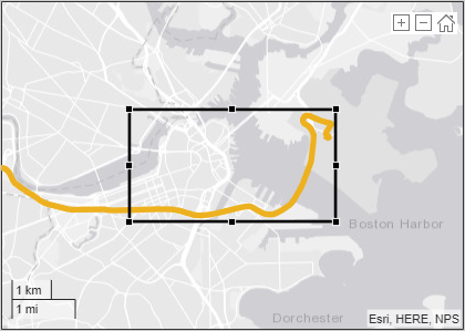
When selecting HERE HD Live Map roads to import from a region of interest, the maximum allowable size of the region is 20 square kilometers. If you specify a driving route that is greater than 20 square kilometers, the app draws a region that is optimized to fit as much of the beginning of the route as possible into the display. This figure shows an example of a region drawn around the start of a route that exceeds this maximum size.
Zenrin Japan Map API 3.0 (Itsumo NAVI API 3.0) — Import Limitations
When you import Zenrin Japan Map API 3.0 (Itsumo NAVI API 3.0) data, the generated road network has these limitations. As a result of these limitations, the generated network might contain inaccuracies and the roads might overlap.
The generated road network uses road elevation data when the Zenrin Japan Map API 3.0 (Itsumo NAVI API 3.0) provides it. Otherwise, the generated network uses terrain elevation data provided by the service.
When the Zenrin Japan Map API 3.0 (Itsumo NAVI API 3.0) service provides information using a range, such as by specifying a road with two to three lanes or a road between 3–5.5 meters wide, the generated road network uses scalar values instead. Consider a Zenrin Japan Map API 3.0 (Itsumo NAVI API 3.0) road that has two to three lanes. The generated road network has two lanes.
Lanes within roads in the generated network have a uniform width. Consider a road that is 4.25 meters wide with two lanes. In the generated road network, each lane is 2.125 meters wide.
Where possible, the generated road network uses road names provided by the Zenrin Japan Map API 3.0 (Itsumo NAVI API 3.0) service. Otherwise, the generated road network uses default names, such as
Road1andRoad2.
Zenrin Japan Map API 3.0 (Itsumo NAVI API 3.0) — Route Selection Limitations
When selecting Zenrin Japan Map API 3.0 (Itsumo NAVI API 3.0) roads to import from a region of interest, the maximum allowable size of the region is 500 square meters. If you specify a driving route that is greater than 500 square meters, the app draws a region that is optimized to fit as much of the beginning of the route as possible into the display. This figure shows an example of a region drawn around the start of a route that exceeds this maximum size.
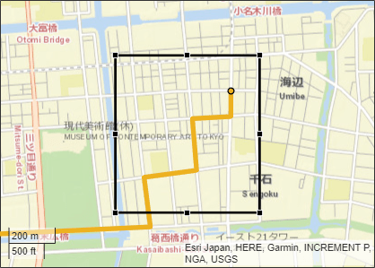
ASAM OpenDRIVE Import Limitations
You can import only lanes, lane type information, and roads. The import of road objects and traffic signals is not supported.
ASAM OpenDRIVE files containing large road networks can take up to several minutes to load. In addition, these road networks can cause slow interactions on the app canvas. Examples of large road networks include ones that model the roads of a city or ones with roads that are thousands of meters long.
Lanes with variable widths are not supported. The width is set to the highest width found within that lane. For example, if a lane has a width that varies from 2 meters to 4 meters, the app sets the lane width to 4 meters throughout.
When you import one-way roads with multiple lane specifications, the app supports only those segment taper positions that match the travel direction of lane. For example, the app supports importing only right taper position for the right lanes. Left or both types of taper position are not supported for right lanes.
Roads with lane type information specified as
driving,border,restricted,shoulder, andparkingare supported. Lanes with any other lane type information are imported as border lanes.Lane marking styles
Bott Dots,Curbs, andGrassare not supported. Lanes with these marking styles are imported as unmarked.
ASAM OpenDRIVE Export Limitations
The cubic polynomial and the parametric cubic polynomial geometry types in the scenario are exported as spiral geometry types. This causes some variations in the exported road geometry if the road is a curved road.
When segments of adjacent roads overlap with each other, the app does not export the overlapping segments of the roads.
When a road with multiple lane specifications contains a taper between two road segments, the app exports the road without taper.
When a road consisting of multiple segments is connected to a junction, the app does not export the road.
The junctions of the road network are processed without lane connection information, so the junction shapes may not be accurate in the exported scenario.
The app does not export any actor that is present either on a junction or on a road with multiple road segments.
When a junction is not connected to any road, the app does not export such junction.
Euro NCAP Limitations
Scenarios of speed assistance systems (SAS) are not supported. These scenarios require the detection of speed limits from traffic signs, which the app does not support.
3D Display Limitations
These limitations describe how 3D Display visualizations differ from the cuboid visualizations that appear on the Scenario Canvas.
Roads do not form junctions with unmarked lanes at intersections. The roads and their lane markings overlap.
Not all actor or lane marking colors are supported. The 3D display matches the selected color to the closest available color that it can render.
Lane type colors of nondriving lanes are not supported. If you select a nondriving lane type, in the 3D display, the lane displays as a driving lane.
On the Actors tab, specified Roll (°) and Pitch (°) parameter values of an actor are ignored. In the Waypoints table, z (m) values (that is, elevation values) are also ignored. During simulation, actors follow the elevation and banking angle of the road surface.
Multiple marking styles along a lane are not supported. The 3D display applies the first lane marking style of the first lane segment along the entire length of the lane.
Actors with a 3D Display Type of
Cuboiddo not move in the 3D display. During simulation, these actors remain stationary at their initial specified positions.
MATLAB Online™ Limitations
These limitations describe the affected functionalities when you use Driving Scenario Designer app in MATLAB Online:
Prebuilt scenarios are not available to load in MATLAB Online.
More About
In driving scenarios, an actor is a cuboid (box-shaped) object with a specific length, width, and height. Actors also have a radar cross-section (RCS) pattern, specified in dBsm, which you can refine by setting angular azimuth and elevation coordinates. The position of an actor is defined as the center of its bottom face. This center point is used as the actor's rotational center, its point of contact with the ground, and its origin in its local coordinate system. In this coordinate system:
The X-axis points forward from the actor.
The Y-axis points left from the actor.
The Z-axis points up from the ground.
Roll, pitch, and yaw are clockwise-positive when looking in the forward direction of the X-, Y-, and Z-axes, respectively.
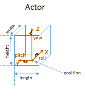
A vehicle is an actor that moves on wheels. Vehicles have three extra properties that govern the placement of their front and rear axle.
Wheelbase — Distance between the front and rear axles
Front overhang — Distance between the front of the vehicle and the front axle
Rear overhang — Distance between the rear axle and the rear of the vehicle
Unlike other types of actors, the position of a vehicle is defined by the point on the ground that is below the center of its rear axle. This point corresponds to the natural center of rotation of the vehicle. As with nonvehicle actors, this point is the origin in the local coordinate system of the vehicle, where:
The X-axis points forward from the vehicle.
The Y-axis points left from the vehicle.
The Z-axis points up from the ground.
Roll, pitch, and yaw are clockwise-positive when looking in the forward direction of the X-, Y-, and Z-axes, respectively.

The origin (that is, the position) of cuboid vehicles differs from the origin of vehicles in the 3D simulation environment. In the 3D simulation environment, vehicle origins are on the ground, at the geometric center of the vehicle.
| Cuboid Vehicle Origin | 3D Simulation Vehicle Origin |
|---|---|
|
|
For nonvehicle actors, the origins are identical and located at the bottom of the geometric center of the actors.
In Simulink, to convert a vehicle from the cuboid origin to the 3D simulation origin, use a Cuboid To 3D Simulation block. For more details about 3D simulation coordinates, see Coordinate Systems for Unreal Engine Simulation in Automated Driving Toolbox.
This table lists the named color options, the equivalent RGB triplets, and hexadecimal color codes that you can use for specifying the color of lanes and markings in a road.
| Color Name | Short Name | RGB Triplet | Hexadecimal Color Code | Appearance |
|---|---|---|---|---|
red | r | [1 0 0] | #FF0000 |
|
green | g | [0 1 0] | #00FF00 |
|
blue | b | [0 0 1] | #0000FF |
|
cyan
| c | [0 1 1] | #00FFFF |
|
magenta | m | [1 0 1] | #FF00FF |
|
yellow | y | [0.98 0.86 0.36] | #FADB5C |
|
black | k | [0 0 0] | #000000 |
|
white | w | [1 1 1] | #FFFFFF |
|
To create a road by using the road function, specify the road centers as a
matrix input. The function creates a directed line that traverses the road centers, starting
from the coordinates in the first row of the matrix and ending at the coordinates in the last
row of the matrix. The coordinates in the first two rows of the matrix specify the
draw direction of the road. These coordinates correspond to the first
two consecutive road centers. The draw direction is the direction in which the roads render in
the scenario plot.
To create a road by using the Driving Scenario Designer app, you can either specify the Road Centers parameter or interactively draw on the Scenario Canvas. For a detailed example, see Create a Driving Scenario. In this case, the draw direction is the direction in which roads render in the Scenario Canvas.
For a road with a top-to-bottom draw direction, the difference between the x-coordinates of the first two consecutive road centers is positive.
For a road with a bottom-to-top draw direction, the difference between the x-coordinates of the first two consecutive road centers is negative.
|
|
|
For a road with a left-to-right draw direction, the difference between the y-coordinates of the first two consecutive road centers is positive.
For a road with a right-to-left draw direction, the difference between the y-coordinates of the first two consecutive road centers is negative.
|
|
|
Lanes must be numbered from left to right, with the left edge of the road defined relative to the draw direction of the road. For a one-way road, by default, the left edge of the road is a solid yellow marking which indicates the end of the road in transverse direction (direction perpendicular to draw direction). For a two-way road, by default, both edges are marked with solid white lines.
For example, these diagrams show how the lanes are numbered in a one-way and two-way road with a draw direction from top-to-bottom.
| Numbering Lanes in a One-Way Road | Numbering Lanes in a Two-Way Road |
Specify the number of lanes as a positive integer for a one-way road. If
you set the integer value as 1, 2, 3 denote the first, second, and third lanes of the road, respectively.
| Specify the number of lanes as a two-element vector of positive integer
for a two-way road. If you set the vector as [ 1L denote the only left lane of the road. 1R and 2R denote the first and second right lanes of the road, respectively.
|
The lane specifications apply by the order in which the lanes are numbered.
A composite lane marking comprises two or more marker segments that define multiple marking types along a lane. The geometric properties for a composite lane marking include the geometric properties of each marking type and the normalized lengths of the marker segments.
The order in which the specified marker segments occur in a composite lane
marking depends on the draw direction of the road. Each marker segment is a directed
segment with a start point and moves towards the last road center. The first marker
segment starts from the first road center and moves towards the last road center for a
specified length. The second marker segment starts from the end point of the first
marker segment and moves towards the last road center for a specified length. The same
process applies for each marker segment that you specify for the composite lane marking.
You can set the normalized length for each of these marker segments by specifying the
range input argument.
For example, consider a one-way road with two lanes. The second lane marking
from the left edge of the road is a composite lane marking with marking types
Solid and Dashed. The normalized range for
each marking type is 0.5. The first marker segment is a solid marking and the second
marker segment is a dashed marking. These diagrams show the order in which the marker
segments apply for left-to-right and right-to-left draw directions of the road.
|
|
|
For information on the geometric properties of lane markings, see Lane Specifications.
A composite lane specification consists of an array of two or more lane specifications for a single road. Each lane specification defines a road segment, which is a section of the road with independent geometric properties, normalized range, and taper.
Each road segment is a directed segment that moves toward the final road center, with the first segment beginning at the first road center, the second segment starting where the first ends, and so on. The range of each road segment is a normalized distance that specifies a proportion of the total length of the road. When a road segment adds or drops lanes from a previous segment, the preceding segment tapers along a specified distance to accommodate the change in number of lanes.
When you render a road with composite lane specifications, the road segments render in the draw direction of the road. For example, consider a one-way road with two road segments and a default normalized range of 0.5 for each road segment. The first road segment contains four lanes and the second segment contains only two lanes. The first segment tapers from four lanes to two lanes, dropping one lane from each side, as it approaches the halfway point of the road, which is the start point of the second segment. These diagrams show the direction in which the road segments render, and how the taper applies to the road, for both the left-to-right and right-to-left draw directions.
|
|
|
For information on the geometric properties of lanes, see Lane Specifications.
Tips
When importing map data, the map regions you specify and the number of roads you select have a direct effect on app performance. To improve performance, specify the smallest map regions and select the fewest roads that you need to create your driving scenario.
You can undo (press Ctrl+Z) and redo (press Ctrl+Y) changes you make on the scenario and sensor canvases. For example, you can use these shortcuts to delete a recently placed road center or redo the movement of a radar sensor. For more shortcuts, see Keyboard Shortcuts and Mouse Actions for Driving Scenario Designer
In scenarios that contain many actors, to keep track of the ego vehicle, you can add an indicator around the vehicle. On the app toolstrip, select Display > Show ego indicator. The circle around the ego vehicle highlights the location of the vehicle in the scenario. This circle is not a sensor coverage area.
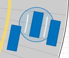
References
[1] European New Car Assessment Programme. Euro NCAP Assessment Protocol - SA. Version 8.0.2. January 2018.
[2] European New Car Assessment Programme. Euro NCAP AEB C2C Test Protocol. Version 2.0.1. January 2018.
[3] European New Car Assessment Programme. Euro NCAP LSS Test Protocol. Version 2.0.1. January 2018.
Version History
Introduced in R2018aStarting in R2018b, in the Camera Settings group of the Driving Scenario Designer app, the Image Width and Image Height parameters set their expected values. Previously, Image Width set the height of images produced by the camera, and Image Height set the width of images produced by the camera.
If you are using R2018a, to produce the expected image sizes, transpose the values set in the Image Width and Image Height parameters.
See Also
Apps
Blocks
- Scenario Reader | Driving Radar Data Generator | Vision Detection Generator | Lidar Point Cloud Generator | Ultrasonic Detection Generator
Objects
drivingScenario|drivingRadarDataGenerator|visionDetectionGenerator|lidarPointCloudGenerator|insSensor|ultrasonicDetectionGenerator
Topics
1 You need to enter into a separate agreement with HERE in order to gain access to the HDLM services and to get the required credentials (access_key_id and access_key_secret) for using the HERE Service.
2 To gain access to the Zenrin Japan Map API 3.0 (Itsumo NAVI API 3.0) service and get the required credentials (a client ID and secret key), you must enter into a separate agreement with ZENRIN DataCom CO., LTD.
MATLAB Command
You clicked a link that corresponds to this MATLAB command:
Run the command by entering it in the MATLAB Command Window. Web browsers do not support MATLAB commands.
Select a Web Site
Choose a web site to get translated content where available and see local events and offers. Based on your location, we recommend that you select: .
You can also select a web site from the following list
How to Get Best Site Performance
Select the China site (in Chinese or English) for best site performance. Other MathWorks country sites are not optimized for visits from your location.
Americas
- América Latina (Español)
- Canada (English)
- United States (English)
Europe
- Belgium (English)
- Denmark (English)
- Deutschland (Deutsch)
- España (Español)
- Finland (English)
- France (Français)
- Ireland (English)
- Italia (Italiano)
- Luxembourg (English)
- Netherlands (English)
- Norway (English)
- Österreich (Deutsch)
- Portugal (English)
- Sweden (English)
- Switzerland
- United Kingdom (English)


